Loading...
Loading...
Loading...
Loading...
Loading...
Loading...
Loading...
Loading...
Loading...
Loading...
Loading...
Loading...
Loading...
Loading...
Loading...
Loading...
Loading...
Loading...
Loading...
Loading...
Loading...
Loading...
Loading...
Loading...
Loading...
Loading...
Loading...
Loading...
Loading...
Loading...
Loading...
Loading...
Loading...
Loading...
Loading...
Loading...
Loading...
Loading...
Loading...
Loading...
Loading...
Loading...
Loading...
Loading...
Loading...
Loading...
Loading...
Loading...
Loading...
Loading...
Loading...
Loading...
Loading...
Loading...
Loading...
Loading...
Loading...
Loading...
Loading...
Loading...
Loading...
Loading...
Loading...
Loading...
Loading...
Loading...
Loading...
Loading...
Loading...
Loading...
Loading...
Loading...
Loading...
Loading...
Loading...
Loading...
Loading...
Loading...
Loading...
Loading...
Loading...
Loading...
Loading...
Loading...
Loading...
Loading...
Loading...
Loading...
Loading...
Loading...
Loading...
Loading...
Loading...
Loading...
Loading...
Loading...
Loading...
Loading...
We are dedicated to addressing any inquiries you may have and providing comprehensive guidance as you navigate the exciting world of 3D printing.
Great question! This will depend on how new you are and how much information you want. We would suggest starting with an
We also have a very helpful on our US webstore that can help guide you to learning what you need to know.
You can find all of our Certifications and Declarations
You can find all of our Safety Data Sheets
You can find all of our Technical Data Sheets
Try out our brand new !
You can find all current profiles and legacy we have made for slicers
Please note it is very difficult to have a full profile list for all material types, on every printer, with each slicing software. We are working hard to improve our profile list, but you may want to check out our active where thousands of members may have already made the profile you need.
Can't find the profile you are looking for? You can .
You can find all basic print tips for all of our products
You should first contact us at [email protected]. Please include all of your order information, full details of the problem you are experiencing, and a photo of the batch number (on spool) or serial number (under dryer dock).
We always stand behind our products and will either troubleshoot or replace.
This Wiki has an amazing where you can ask any question you have, or even have a full conversation in order to find the answers you need! It knows everything that is on this Wiki so you can ask it what is the right material for your project, how can you fix a particular printing issue, or give you tips on 3D printing in general. Just click the "Ask" Icon at the top of this page or hit "CTRL + I" on your keyboard.
A slicer is specialized software that converts 3D models into printable instructions (G-code) for FDM printers. It "slices" digital designs into horizontal layers, calculates toolpaths, and defines parameters like print speed, temperature, and material flow. Slicers enable precise control over print quality, material efficiency, and structural integrity.
Model Import: Accepts 3D files (STL, OBJ, STEP, etc.) to define geometry.
Layer Segmentation: Divides the model into layers based on user-defined layer heights (e.g., 0.1mm–0.3mm).
Toolpath Generation: Maps extruder movements, including infill patterns, supports, and adhesion aids.
Key features include infill density optimization, support structure generation, and print speed adjustments for balancing quality and efficiency.
Launch Cura on your computer.
In the top menu, click Preferences, then select Configure Cura. This opens the main configuration panel where you can manage profiles and materials.
On the left side of the configuration panel, click Profiles to see your current list of available print profiles.
This process is very similar to :
Open Orca Slicer on your computer.
Go to the top menu and select File, then choose Import, followed by Import Configs.
In 3D printing, the term "jerk" has a different practical meaning compared to its classical definition in engineering and physics. Traditionally, jerk is defined as the rate of change of acceleration—a third derivative of position with respect to time, measured in units like mm/s³. It describes how quickly acceleration itself changes, which is a highly dynamic, instantaneous measure important in motion control and mechanical systems.
However, in 3D printing firmware and motion control, "jerk" is commonly used as a simplified setting representing the instantaneous allowable speed change of the printer's print head when changing direction, measured in mm/s (velocity units, not acceleration units). It effectively sets a threshold speed—the maximum speed at which the printer can change direction without needing to decelerate to a full stop first. For example, if the jerk is set to 20 mm/s, the printer can instantly reverse or turn at that speed without slowing down completely, enabling smoother and faster cornering movements. This usage is more about limiting abrupt speed changes in the axes at junctions or corners rather than describing physical jerk as acceleration changes. Thus, in 3D printing, jerk controls how quickly the print head can pivot direction, affecting print speed, quality, and mechanical vibrations, rather than representing true "jerk" from physics.
An interesting phenomenon in 3D printing is that what you set your printing temperature at may not be what the temperature of your actual filament extrudes at.
We cover this in our section in Material Science, but essentially it takes time for material to heat up. This means if you print faster than the hotend can melt your material, you will extrude at a lower temperature than what you set in your slicer.
Extrusion Temperature: The temperature at which the plastic exits the nozzle (in ˚C)
Extrusion Rate: The rate at which the plastic is extruded from the nozzle (in mm3/s)
This is why when you print really fast on a printer that does not have a very high flow hotend - you may need to set your printing temperature above manufacturer recommendations. If you extrude at too low of a temperature due to print speeds, you may get a part that has a matte finish, under extrudes, or potentially even clogs.
To effectively dry your filament and achieve optimal results, having good airflow is far more important than simply increasing the temperature. This is because drying filament is primarily about removing the moisture trapped inside the material, and airflow plays a critical role in carrying away that moisture once it evaporates. As the saying goes, "you don't dry your hair by putting it in the oven," highlighting that excessive heat alone is not the answer and can even damage the filament if temperatures are too high.
By ensuring consistent and strong airflow, you can accelerate the drying process at a lower temperature, which is gentler on the material and helps maintain its quality. Good airflow allows moisture to escape efficiently, preventing it from lingering around the filament and causing issues like brittleness or poor print results. Overall, drying filament with proper airflow means you can dry it more quickly and safely, minimizing the risk of overheating while effectively preparing your filament for smooth, reliable 3D printing.
Using a larger nozzle in 3D printing can result in better layer adhesion primarily due to the increased extrusion width and thicker layers. When the nozzle diameter is larger, it deposits a wider bead of molten filament, which creates a greater surface contact area between successive layers. This increased area facilitates better bonding as more molten material from one layer fuses into the previous layer, enhancing the overall mechanical strength of the print. Thicker layers associated with larger nozzles also mean fewer total layers in the print, which reduces the cumulative number of potential weak interfaces that could cause delamination or layer separation. Therefore, parts printed with larger nozzles often demonstrate improved inter-layer strength because there are simply fewer opportunities for adhesion failures across layers.
Importing a profile onto a slicer will be different depending on the slicer you are using. For the example below we will use Bambu Studio.
After downloading your profile from our list, you will open up Bambu Studio. You then click on "File" on the top left:
You then scroll over "import" and click "Import Configs"
You will then either choose the Zip file or the .bbsflmt file you just downloaded. If the profile you downloaded is a Zip file - you would choose the zipped compressed folder without uncompressing.
Your profile will now be listed under "User Presets" "Custom"
This Wiki is built with a very advanced where you can ask anything you want to know about. Just click the "Ask" icon at the top of this page, or hit "CTRL + I" on your keyboard.
This includes asking:
Just explain your application needs and ask the AI bot what material it suggests.
Composite 3D printing remains an exciting and relatively untapped area within the 3D printing world. While it has not yet been fully explored or mainstreamed, the ongoing development and increasing availability of multi-tool and multi-material printers are paving the way for truly innovative and complex composite prints. As these advanced machines become more accessible, we can expect to see groundbreaking combinations of materials that were previously impossible or impractical to combine, pushing the boundaries of what 3D printing can achieve.
At its core, composite 3D printing involves using two or more distinct materials within a single print to produce parts that possess enhanced or hybrid properties, leveraging the strengths of each individual material. For example, by combining flexible TPU with rigid PLA in one object, engineers can create components that are not only strong and durable but also capable of withstanding impact and absorbing energy—so much so that such prints can even stop a bullet in certain experimental applications. This ability to tailor mechanical, thermal, or chemical properties on a layer-by-layer basis opens up exciting opportunities in fields ranging from protective gear to custom medical devices and beyond. As the technology matures, composite 3D printing is set to revolutionize how we think about material performance and design freedom.
Over-extrusion in 3D printing is generally easier to detect with the naked eye than under-extrusion. When too much filament is extruded, you often see obvious signs like blobs, stringing, or excessively thick layers where the filament appears to spill or ooze beyond the intended boundaries. These visual cues—such as raised ridges between surface lines or drooping layers caused by excess material—make over-extrusion relatively straightforward to identify. The surface of the print may look messy or oversized, which indicates that the printer is pushing out more material than necessary.
In contrast, under-extrusion can be subtler visually but can have a more serious impact on print strength. Even if an under-extruded part looks acceptable on the surface, missing or thin filament deposition means the layers are not fully bonded, and the internal structure can be fragile. This results in prints that crumble, crack, or tear more easily under stress, since insufficient filament compromises the object's mechanical integrity. Gaps between layers or sparse infill may not always be immediately apparent, but they weaken the part significantly. So while under-extrusion can be harder to spot at a glance than over-extrusion, it poses a greater risk to the durability and functionality of the final print. Monitoring print quality with attention to detail is necessary to avoid these hidden weaknesses.
This means visual inspection alone might not detect under-extrusion sufficiently, making calibration and careful tuning essential for strong, reliable 3D prints. Over-extrusion errors warn you visually that something is wrong, but under-extrusion can quietly degrade part quality even if it looks good initially.
The first layer of a 3D print is arguably the most critical, as it sets the foundation for the entire part. If the first layer does not adhere properly to the build plate or is unevenly extruded, the print can fail as subsequent layers rely on a stable and consistent base. Too large a gap between the nozzle and the bed can lead to poor adhesion, resulting in warping or layer shifting, while a nozzle too close to the build plate risks scraping or damaging the surface, potentially ruining both the plate and the print. A well-laid first layer ensures proper bonding and dimensional stability, significantly increasing the chances of a successful print.
Modern 3D printers have made significant advancements with features like automatic bed leveling and initial Z-height calibration, which greatly reduce the chances of first layer issues and save users from manual tweaking. These automated systems help ensure the nozzle height and bed level are optimized before printing starts. However, despite these improvements, it is still highly recommended to monitor the first layer closely, especially when trying a new material, changing build plates, or printing after maintenance. Confirming the first layer prints correctly before leaving the printer unattended remains best practice to prevent print failures and protect your hardware.
Currently, we do not have any data confirming that any 3D printing material is FDA food-safe. In fact, no 3D printing material on the market holds FDA food-safe certification. This is because food safety certification applies not only to the raw material but to the final printed object itself. Factors such as the object's shape, the type of build plate used, the printing environment, and the entire manufacturing process all affect whether the object can be deemed food-safe. At present, the FDA does not offer a specific certification tailored for 3D-printing materials.
Even if the filament material itself is considered food-safe, the 3D printing process usually compromises that safety. The layered nature of fused filament fabrication creates microscopic gaps and crevices between layers, which can easily harbor bacteria and contaminants. These tiny spaces make thorough cleaning extremely difficult, so while the object might be safe for a single use, reliably sanitizing it for repeated food contact is challenging. Additionally, the use of brass nozzles in printing can introduce another safety concern. Brass contains lead, and during the printing process, small amounts of lead may be transferred onto the surface of the print. This contamination makes the printed part potentially unsafe for food use as well. Because of these factors—including material, process, and equipment—it is important to approach 3D-printed objects with caution when considering them for any food-related application, often necessitating additional post-processing, sealing, or certification to ensure safety.
Fused Deposition Modeling (FDM) and Fused Filament Fabrication (FFF) describe the same 3D printing process, which involves extruding thermoplastic filament layer by layer to build a part. The method has become one of the most widely used additive manufacturing techniques because of its relatively low cost, material availability, and accessibility to both hobbyists and professionals. Despite the different names, the underlying process is identical in both cases.
The distinction between the terms comes from intellectual property rather than technology. Fused Deposition Modeling was coined and trademarked by Stratasys, one of the pioneering companies in the 3D printing industry. Because the name is protected, the broader community, particularly in the open-source sector, adopted the term Fused Filament Fabrication to describe the same process without infringing on trademark rights.
Today, both FDM and FFF are used interchangeably to describe extrusion-based 3D printing. In commercial and industrial contexts, FDM may be more common, especially when referring to Stratasys machines, while FFF is often seen in reference to open-source or consumer-grade printers. Regardless of terminology, the technology refers to the same foundational process in additive manufacturing.
G-Code Export: Generates machine-readable instructions for the printer.
Click the Import button at the bottom of the Profiles tab.
A file browser window appears. Navigate to the profile file you wish to import (typically .curaprofile or .json format) and select it. Click Open.
Cura will show a dialog confirming the imported profile. You will now see the new profile listed under Custom Profiles.
Click the Activate button on your new profile to begin using it for slicing prints.
If you want to access more or advanced settings, in the Profiles section, you can check or uncheck which parameters display during regular use.
To use the imported profile, make sure it’s selected before you prepare or slice your next model.
These steps will look very similar across current Cura versions. The interface is straightforward, with dialogs or panels appearing as you follow each menu path and choose your import option.
Select the profile files you wish to import, then click Open.
Orca Slicer will prompt you if the profiles already exist. Confirm overwrite if necessary.
Once imported, your profiles will appear in the relevant section (printer, filament, or process) and can be selected for use with compatible printers or materials.
For filament profiles, check dependencies tabs if you don’t see them available for all nozzle sizes and assign them as needed.
This process allows quick migration or setup of custom profiles, and works for most versions of Orca Slicer.
That's right - if the document exists on this Wiki - the bot will help you find it.
Wondering the material with the best HDT? The best impact strength? Ask away!
Just explain your issue and the bot will help diagnose the problem!
Ask the bot anything at all and feel free to let us know how it did! This is still a new feature and we would love your feedback. Shoot as an email anytime at [email protected] with how it did!
Open ideaMaker on your computer.
Click the Library button in the top toolbar to access the ideaMaker Library.
Browse or search in the Library for the slicing profile you want to import.
On the profile detail page, click “Import to ideaMaker.”
A pop-up will appear asking you to copy the import link; click Copy.
Return to ideaMaker; a template download window should open automatically.
Click “Download” to fetch the slicing profile file.
After downloading, click “Next” to open the Import Slicing Template window.
Fill in any project details as needed; the basic info will auto-fill.
Select whether to import the profile to an existing printer or create a new printer profile.
If importing to an existing printer, select it from the drop-down menu.
If creating a new printer, edit settings as required in the prompted interface.
Assign filament profiles if the slicing profile corresponds to specific filaments, or create new filament profiles as needed.
Save the template settings to complete the import.
If the download window does not open automatically, enable monitoring clipboard downloads in Preferences or manually paste the import link in the import dialog.
The imported profile will now be available for slicing with the selected printer and filament.
This method leverages ideaMaker’s integration with its online Library but local imports of .bin files are also supported via the Template menu. The interface provides onscreen prompts guiding you through each step


Layer height significantly impacts print quality and duration, with optimal ranges dictated by nozzle diameter. A 0.1mm layer height triples print time compared to 0.3mm when using the same nozzle and speeds, as it requires three times the number of layers. Reliable results are achievable within 25–75% of the nozzle diameter (though some suggest 20-80%):
Example: A 0.4mm nozzle performs best at 0.1–0.3mm layer heights.
Quality vs. Speed: Thicker layers reduce detail in the Z axis but accelerate printing, while thinner layers enhance Z resolution at the cost of time.
Print duration also influences failure likelihood. Longer prints increase exposure to environmental variables (e.g., temperature shifts, power interruptions). Additionally, extrusion speeds often need reduction for thinner layers to prevent nozzle clogs or under-extrusion. Conversely, very large layer heights may also require reduced speed due to the max volumetric speed of your material and/or hotend.
Generally speaking - modern printers are not as affected by what is covered below, but it still can be beneficial to understand it.
Layer height precision is affected by Z-axis leadscrew/threaded rod specifications, including pitch and motor step angle. Mismatched settings can introduce inconsistencies due to mechanical rounding errors. For example:
M8 Leadscrew (2mm pitch): Adjustable in 0.01mm increments with a 1.8° stepper motor.
M5 Leadscrew (0.8mm pitch): Requires adjustments in 0.014mm increments for optimal precision.
These tolerances matter most on budget machines, where hardware limitations amplify imperfections. While deviations from calculated values may yield acceptable results, adhering to mechanical constraints ensures maximum consistency.
The initial layer height prioritizes adhesion over detail. A thicker first layer (up to 75% of nozzle diameter) improves bed bonding by increasing material deposition. For example:
0.4mm Nozzle: Initial layers up to 0.3mm enhance adhesion.
0.15mm Nozzle: Maximum initial layer of 0.11mm demands extreme precision, magnifying build plate leveling challenges.
Smaller nozzles exacerbate first-layer difficulties due to reduced tolerance for Z-height miscalibration.
Line width typically matches the nozzle diameter, but adjustments can address specific needs:
Standard Practice: A 0.4mm nozzle uses 0.4mm line width.
Experimental Tweaks: Increasing line width by 10% (e.g., 0.44mm on a 0.4mm nozzle) may improve surface finish but risks over-extrusion. For drastic changes, switching nozzles is often preferable.
Top/Bottom Line Width adjustments can resolve gaps in upper layers. Reducing this setting slightly (e.g., 0.35mm on a 0.4mm nozzle) encourages tighter extrusion paths, minimizing voids on flat surfaces.
While most slicer settings (e.g., wall thickness, infill density) remain unchanged for general use, niche scenarios may warrant adjustments:
Material-Specific Tuning: Flexible filaments like TPU often require reduced speeds and increased line widths to prevent buckling.
Hardware Limitations: Budget printers benefit from conservative layer heights (e.g., 0.2mm) to mitigate Z-axis inaccuracies.
The 3D printing community continually refines best practices, encouraging experimentation with slicer parameters. Documenting successful adjustments ensures reproducibility across projects.
Layer Height: Balance speed and quality within 25–75% of nozzle diameter.
Z-Axis Hardware: Match layer heights to leadscrew pitch for precision.
Initial Layer: Prioritize adhesion with thicker first layers.
By understanding these principles, users can optimize prints for efficiency, reliability, and quality across diverse applications.
Download the slicer profile you want to use, making sure it’s compatible with your slicer and printer model. The file is often in formats like .ini, .json, .3mf, .zip, or a specific profile extension.
Open your slicer software and find the menu option for importing profiles—this is usually under “File” or “Settings,” then “Import” or “Profiles.”
Select “Import,” then browse to and select your downloaded profile file.
Confirm the import; your new profile should appear in the list of available print, filament, or machine profiles, ready to be selected for your next print job.
For some slicers, you may need to activate or assign the profile to a printer or filament type after importing.
Always double-check print settings after importing to ensure compatibility with your printer and material, as profiles are sometimes designed for specific setups.
Following these steps works for popular slicers such as , , , , and .
Dual-color filaments create striking visual effects by blending two fixed colors along a single strand. These filaments are not randomized; instead, one color runs along one side of the strand, and the other color sits on the opposite side. The strand itself is slightly oval-shaped to help maintain its orientation as it feeds into the extruder. While simple in concept, achieving consistent color alignment requires careful control of your printer’s mechanics and settings.
One of the most common causes of color swapping is loose extruder tension. If the filament strand slips or rotates slightly as it passes through the drive gears, it can flip 180 degrees, causing the colors to reverse mid-print. Tightening the extruder tension just enough to grip the filament firmly without deforming it will greatly reduce this risk. It’s worth making small adjustments between prints until the filament feeds smoothly and consistently.
Keep your inner and outer wall speeds as close as possible. Large differences in print speeds between these walls can create fluctuations in extrusion pressure inside the nozzle. Those pressure changes may cause slight filament rotation, leading to unwanted color flips. As a general rule, keep the difference in wall speeds below 20%, or ideally identical for fine, surface-visible prints.
Consistency is key with dual-color material. Frequent or large shifts in print speed—such as between infill, walls, and top layers—can also cause inconsistent extrusion pressure. Aim to set most of your print speeds within a narrow range to maintain smooth, stable extrusion. This helps keep both the color alignment and the overall surface finish more uniform.
Dual extrusion materials should be able to be used in an AMS like system - but the added length needed to reach the extruder along with any extra twists or turns to reach that exctruder can lead to swaps being more likely. Just be careful when using an AMS.
Small tuning changes can make a noticeable difference. Retraction that’s too aggressive can cause minor twisting of the filament inside the drive path, while insufficient flow may reduce filament pressure stability. Adjust these parameters gradually while observing prints with strong directional color lines.
Since dual-color strands rely on a fixed orientation, any kinking or twisting of the spool can introduce tension that leads to flipping during printing. Keep your filament neatly wound, store it with minimal crossovers, and unwind it gently before loading.
When 3D printing, layer height and part thickness can influence more than just strength and weight. The thickness of a print plays an important role in how well it holds its shape under heat, whether during service use or during post-processing such as annealing. Heat deflection temperature (HDT) is often discussed when comparing materials, but the print’s geometry and density also have a large effect on real-world performance.
Thin-walled or low-density prints are more prone to warping and deformation when exposed to heat. Because the structure has less material to resist internal stresses, it will soften faster and lose its shape more easily. This is especially noticeable when annealing thin models since the plastic relaxes as internal stresses are released.
For this reason, extra measures should be taken when working with and annealing thin parts. Two common methods are salt annealing or sand annealing, where the print is buried in fine grains to hold it in place while it heats. If the print is flat, placing a weight on top can help keep it from bowing or curling during the process. These methods reduce unwanted distortion and allow the heat treatment to improve thermal resistance without losing dimensional accuracy.
Thicker, denser parts behave differently under heat. Because they have greater bulk and structural integrity, they are more resistant to softening and warping during exposure. A heavy, solid print will generally hold its shape without needing to be supported during annealing. While the annealing process can still improve heat resistance by increasing crystallinity in certain materials, the odds of geometric deformation are much lower compared to thin-walled prints.
The heat resistance of a printed object cannot be determined by material rating alone. While HDT gives useful baseline information, geometry and thickness contribute to how that object will perform in practice. A thin tray and a solid block made of the same filament can show very different behaviors when placed under heat. Understanding this relationship makes it possible to choose the right print settings, infill, and post-processing method to get the desired thermal performance.
Many people in the 3D printing community often consider standard PLA to be a weak or fragile material. However, this perception doesn’t tell the full story. In reality, standard PLA exhibits impressive strength in several important mechanical aspects. It is known for being very rigid and having good tensile strength, allowing it to withstand substantial loads and maintain its shape under pressure. This makes PLA well-suited for many applications where stiffness and dimensional stability are critical.
The misconception about PLA’s weakness largely stems from its relatively low impact resistance. While PLA can handle steady forces and tension well, it is more prone to cracking or breaking when subjected to sudden impacts or drops. This means that although a PLA print might not bend or deform easily under normal use, it can be brittle when faced with sharp shocks or accidental falls. Therefore, impact resistance is just one way to measure material strength, and PLA’s excellent rigidity and tensile capabilities mean it can be quite strong when used in the right contexts and for parts designed to avoid impact stresses.
If you notice that one section of your print appears more matte compared to other areas, it’s often a sign that you are printing too quickly for the particular hotend and material combination you’re using. Certain materials are not designed for high flow rates and can develop a dull, matte finish when pushed beyond their optimal extrusion speed. This happens because the filament doesn’t have enough time to fully heat up to the designated temperature, resulting in incomplete melting and less glossy surface quality.
To maintain a consistent shiny finish while printing at higher speeds, it’s important to use materials specifically formulated for high flow applications along with a hotend capable of handling those flow rates. High flow hotends allow the filament to heat more efficiently and extrude smoothly even at faster speeds, helping preserve the intended surface appearance. Balancing the right material, hotend, and print speed is key to achieving fast prints without sacrificing aesthetic quality.
When orienting prints on the build plate, it’s common practice to prioritize factors like achieving the best overhang quality and minimizing the amount of support material needed. While these considerations are important for print quality and efficiency, they are not the only elements to keep in mind when deciding on the print orientation. One crucial factor that is often overlooked is the mechanical strength of the printed part, which is inherently influenced by the layer-by-layer nature of 3D printing.
Because 3D prints are created by stacking layers of material, parts typically exhibit their weakest mechanical strength along the Z axis—perpendicular to the layers—making them more prone to breaking or delaminating along those layer lines. As a result, if you're printing a part that must withstand mechanical stress or structural loads, it’s essential to carefully consider the orientation not only during printing but also during the design phase. By aligning the print so that the greatest stresses are along the X or Y axes (parallel to the layer lines), you can significantly improve the part’s durability and performance. Taking print orientation into account from the start can help ensure the final object meets both functional and strength requirements.
Fused Deposition Modeling (FDM) is the most widely used form of 3D printing in households around the world. This process involves extruding melted thermoplastic material layer by layer, allowing each layer to cool and solidify before the next one is added.
FDM is an additive manufacturing method, opposite to subtractive processes like CNC milling. Instead of cutting away from a solid block, FDM uses only the material needed for the part itself, with the exception of support structures used for overhangs. These supports are removed and discarded after printing.
The uniqueness of FDM printing primarily lies in three key areas: the material used, the slicing software that converts 3D models into G-code instructions, and the extrusion system. Other components like motors and control boards are not exclusive to FDM and are common across many digital fabrication methods.
FDM printing is considered one of the most affordable and accessible methods of 3D printing. Compared to other technologies, such as SLA or resin printing, both the machines and materials are more cost-effective. While resin printer prices have dropped in recent years, they generally offer smaller build volumes and involve more expensive consumables, and are generally less user friendly.
The material variety available for FDM is extensive. Options include flexible filaments, carbon fiber blends, nylon, polycarbonate, UV-resistant, and weather-resistant materials. Many high-temperature materials are also available, though they often require enclosed and actively heated environments. With hundreds of filament types on the market—each offering unique characteristics like strength, flexibility, and thermal resistance—it is possible to find a material suited to nearly any application, provided the printer is equipped with a compatible extruder and hotend.
Compared to resin-based printing processes, FDM is also much cleaner and easier to use. It avoids handling of toxic chemicals and typically involves less post-processing. This makes FDM a more beginner-friendly option and better suited for casual or home use.
In FDM 3D printing, axis orientation may be unfamiliar to those with a background in geometry or general mechanics. The X-axis moves the tool left to right, the Y-axis moves it forward and backward, and the Z-axis controls vertical movement. Though it may seem counterintuitive, this naming convention is standard within the 3D printing community.
The most common axis configurations are based on Cartesian and CoreXY designs. Cartesian printers operate with each axis independently controlled by its own stepper motor. Typically, the build plate moves in the Y direction, while the hotend moves in the X direction. The entire carriage moves in the Z direction. These printers are often referred to as “bed slingers.”
Some machines, such as the Ender 5 series, use Cartesian-style motor movement but have a vertically moving build plate. These are often grouped with “gantry-style” printers for simplicity. In general, printers where the bed moves vertically in the Z-axis are considered gantry-style, while those where the bed moves forward and backward in the Y-axis are considered Cartesian-style or more colloquially as "bed slingers".
CoreXY machines differ in that the X and Y axes are synchronized through a belt system driven by two stepper motors. This allows for smoother motion, reduced Z-wobble, and improved stability—especially during faster printing. CoreXY printers are gaining popularity due to these benefits and are now found in models like the Bambu Lab X1 and P1 series.
Printers such as the A1 and A1 Mini continue to use Cartesian-style configurations and are known as "bed slingers".
Delta printers operate on an entirely different principle, using three arms arranged in a triangle to position the extruder above the print bed. While they can offer high-speed printing and excellent quality, they require taller frames and are less compact than Cartesian or CoreXY alternatives. These machines are far less commonly used due to space and setup requirements, but they are capable of excellent results.
FDM printers use one of two extruder types: direct drive or Bowden. A direct drive extruder feeds filament directly into the hotend from a motor mounted on the print head. In contrast, a Bowden extruder uses a remote motor to push filament through a PTFE tube to the hotend.
Bowden systems reduce the weight of the print head, allowing for faster movement. However, they can struggle with materials like TPU (flexible filament) and often require precise tuning of retraction settings to avoid stringing. Direct extruders offer better precision, easier use with flexible materials, and generally improved extrusion control.
Recent industry advances, such as vibration compensation, have made the weight disadvantage of direct drive systems less significant. As a result, more manufacturers are now offering affordable models with direct drive setups, and Bowden configurations are becoming less common.
Read more about .
Fused Deposition Modeling (FDM) is an additive 3D printing process that extrudes melted thermoplastic material layer by layer, allowing each layer to solidify before adding the next.
Unlike subtractive methods like CNC milling, FDM only uses material needed for the part plus temporary supports, making it efficient and low waste.
FDM printing depends on three main factors: the filament material, the slicing software that produces G-code, and the extrusion system; other components like motors are shared with other fabrication types.
Cardboard spools have several advantages over plastic spools that make them an appealing choice for many in the 3D printing community, despite some ongoing debate. One key benefit is their durability in terms of impact resistance—they do not shatter or crack when dropped, unlike plastic spools which can break. This toughness makes cardboard spools more resilient during handling and transportation. Additionally, cardboard spools can typically withstand higher temperatures before deforming, which is especially useful when drying filament spools prior to printing. Plastic spools may warp under such heat, whereas cardboard maintains its form better, allowing safer and potentially more effective moisture removal.
Another important advantage of cardboard spools is their environmental friendliness. Many cardboard spools, such as those produced by Polymaker, are made from recycled materials and are fully recyclable themselves. This contributes to reducing plastic waste and the overall carbon footprint associated with 3D printer filament packaging. They are lighter as well, which lowers shipping emissions. Cardboard spools represent a more sustainable option, aligning with the growing awareness of environmental impacts in 3D printing. Polymaker’s use of recycled cardboard further enhances this benefit, providing users with an eco-conscious choice without sacrificing functional durability.
Shell walls in 3D printing define the outer perimeters of a printed object, directly influencing structural integrity, surface quality, and dimensional accuracy. These walls are composed of one or more contiguous layers (lines) extruded around the model’s exterior. Proper configuration ensures optimal strength, minimizes defects, and balances material usage.
The image below is a printer in a Cartesian setup, where the build plate moves back and forth in the Y direction and the hotend left and right in the X direction – similar to the popular Bambu Lab A1, Creality Ender 3, and Prusa MK4 printers.
Z Carriage: This connects to both the Z rod and threaded rod/leadscrew. The leadscrew then turns due to the stepper motor it is attached to, which then moves the x carriage up and down. On Bowden machines this is often where the extruder is attached.
X Endstop: This is what tells the hotend to stop when homing. There is also a Y and Z endstop not shown in this picture which have the same function (though a Z endstop may be replaced by an auto bed leveler).
Print quality and printing time depend on several factors, with nozzle diameter and layer height having the most significant impact.
Nozzle diameter determines the line width of printed segments, which affects tolerances in the X/Y direction. While some users adjust line width slightly, maintaining the same value as the nozzle diameter is common. Experimenting with a 10% increase has produced favorable results (e.g., printing a 0.44mm line width with a 0.4mm nozzle).
Maintaining a 3D printer involves regularly scheduled tasks and readily available supplies to prevent issues and ensure optimal performance. Certain tools are used frequently, while others are reserved for occasional maintenance.
Specific tools enhance 3D printing and printer maintenance.
3MF: A newer file format designed specifically for 3D printing. It is basically G-code along with other relevant slicing information so that you can open a 3MF file into a slicer.
Aluminum Extrusion Rails: These have your carriages move along aluminum extrusion bars via rollers (as compared to Linear Rails or Linear Rods). Think of the original Ender 3 as an example.
Barrel: A heatsink attached to your hotend which is meant to keep a temperature differential from said hotend. The barrel is cooled by a fan and will make sure your filament is only being heated in the hotend and not creeping upward.
Bowden Extruder: An indirect extruder – where the extruder is not directly attached to the hotend and must feed filament over a distance to reach the hotend.
Brim: Lines of print that are touching the perimeter of your print on the build plate. This helps to anchor your part if you think it may warp or get knocked off.
Also known as Polyethylene Terephthalate Glycol
This glycol-modified version of PET plastic combines the best traits of its counterparts, offering ease of use and versatility. Whether you’re crafting functional prototypes or parts requiring chemical resistance, PETG is a filament worth mastering. Let’s explore what makes it a favorite among makers and professionals alike.
PETG is a thermoplastic derived from PET (the same plastic used in water bottles), modified with glycol to enhance flexibility and reduce brittleness. This adjustment makes it more suitable for 3D printing, as it improves layer adhesion and reduces shrinkage during cooling. PETG’s unique blend of properties bridges the gap between PLA’s user-friendliness and ABS’s higher heat resistance, making it ideal for projects that demand both slightly higher heat resistance, chemical resistance, and practicality.
FDM 3D printing has unlocked a fascinating paradox: the ability to create machines that can, in turn, create more machines. From extruder assemblies to enclosures, hobbyists and engineers now use FDM to fabricate custom 3D printers tailored to specific needs—whether ultra-fast CoreXY systems, multi-material tool-changing setups, or industrial-grade enclosures. This self-replicating capability has roots in the RepRap movement, which pioneered open-source 3D printers in the 2000s, but modern advancements like Voron builds and modular tool changers have pushed the concept into new realms of precision and customization.
Also known as Acrylonitrile Butadiene Styrene
Acrylonitrile Butadiene Styrene (ABS) has long been a cornerstone of both industrial manufacturing and 3D printing. Known for its toughness, heat resistance, and versatility, ABS filament bridges the gap between everyday usability and engineering-grade performance. From LEGO bricks to automotive components, this material’s balance of strength and flexibility makes it a favorite for functional parts that demand durability and added heat resistance.
ABS is a thermoplastic polymer composed of acrylonitrile, butadiene, and styrene, combining rigidity, impact resistance, and thermal stability. Unlike PLA, which is derived from plant-based sources, ABS is petroleum-based, giving it higher heat tolerance and mechanical resilience. Its amorphous structure allows it to soften gradually when heated rather than melting abruptly, making it suitable for repeated thermal processing.
3D printers are categorized by their motion systems, which dictate how the print head and build platform move during printing. Among various motion systems, the three primary types are Cartesian, CoreXY, and Delta. While other motion systems exist, these three are the most common and widely used in desktop 3D printing.
Besides Cartesian, CoreXY, and Delta, there are other motion systems such as Polar printers, SCARA (Selective Compliance Assembly Robot Arm) printers, continuous belt, and H-Bot systems. However, these are less common in consumer and hobbyist 3D printers.
Nylon, also known as polyamide (PA), is a family of thermoplastic polymers valued in FDM 3D printing for their strength, flexibility, and wear resistance. Despite their appealing mechanical properties, nylon filaments are among the most challenging materials to print due to their high printing temperatures, tendency to warp, and strong affinity for moisture. Several nylon types are formulated for FDM printing, each with distinct characteristics that influence print quality, mechanical performance, and ease of use.
PA6 is one of the most common nylons used in FDM printing. It is a tough material with high tensile strength and excellent impact resistance, making it suitable for functional parts and mechanical components. However, PA6 absorbs moisture quickly from the air, which can lead to bubbles and poor layer adhesion if not properly dried. It also has a strong tendency to warp unless printed with a heated bed and enclosed chamber. Typical extrusion temperatures range from 250°C to 270°C. After annealing, PA6 parts gain improved dimensional stability and heat resistance due to increased crystallization.
Tree supports and normal (or linear) supports represent two distinct types of support structures used in 3D printing to handle overhangs and complex geometries, each with their own pros and cons. Tree supports grow organically around the model, starting with a thick base on the build plate and branching out to support overhangs only where necessary. This tapered, hollow design uses less filament and typically reduces print time compared to normal supports. Because tree supports touch the model at fewer points—often just at the tips of their branches—they generally cause less surface damage and are easier to remove. Additionally, since tree supports primarily attach to the build plate rather than the print itself, there is a lower chance that support material will be deposited directly atop the model, improving the final surface finish on supported areas. However, tree supports have less surface area to support overhangs, which can sometimes result in weaker support for delicate features or a worse looking underside of your print. They are also more prone to being knocked off the build plate during printing, especially if the base is narrow or the print is tall and wobbly.
Normal supports, on the other hand, consist of vertical structures printed straight up from the build plate directly underneath overhangs. These supports provide a larger contact surface area with the underside of overhangs, often leading to better overhang quality by offering solid, stable backing during printing. They are less likely to detach from the build plate mid-print, providing more reliable support for heavy or extensive overhang areas. The downside is that normal supports consume more filament and typically lengthen print times due to their denser, solid design. Moreover, normal supports often touch the print’s upper surfaces, which can leave marks or require more post-processing to achieve a smooth finish.
Make sure you have downloaded your profile files, which are usually in .ini, .gcode, or .3mf format. Extract the files if they come in a zip.
Launch PrusaSlicer and look for the top menu bar.
Click File, then select Import.
When selecting 3D printing materials for electrical insulation applications, understanding key electrical properties such as dielectric strength and dielectric constant is essential. These properties determine how well a material insulates against electrical voltage and how it interacts with electrical signals, impacting safety, signal integrity, and overall performance.
Dielectric strength measures how much voltage a material can withstand per millimeter before electrical breakdown occurs, essentially how well it resists electricity passing through it. A higher dielectric strength indicates better insulating capability. Fiberon PPS-GF20, reinforced with 20% glass fiber by weight (GF), exhibits a dielectric strength of approximately 6.05 kV/mm. This is about 12 times higher than Fiberon PPS-CF10 (carbon fiber reinforced), which has 0.45 kV/mm. The significantly elevated dielectric strength of PPS-GF20 makes it highly suitable for moderate voltage insulation, ensuring safer operation compared to carbon fiber reinforced materials or air in many applications.
Setting your maximum volumetric speed (MVS) is a crucial step in optimizing 3D print quality and preventing under-extrusion. Volumetric speed represents the rate at which your printer’s hotend can reliably melt and extrude filament, measured in cubic millimeters per second (mm³/s). When you set a cap on the MVS in your slicer, your printer will automatically adjust the movement speed based on your chosen layer height and line width. The slicer calculates the resulting maximum speed using the formula: Print Speed (mm/s) = Volumetric Flow Rate (mm³/s) / (Layer Height (mm) × Line Width (mm))
You can also use handy calculator.
If you increase either the layer height or line width (common with larger nozzles), the maximum print speed is automatically reduced to prevent exceeding the hotend’s capacity. For example, with a higher layer height or wider extrusion, your print speed must decrease to maintain the same volumetric flow, ensuring consistent, high-quality extrusion and avoiding issues like gaps, jams, or weak prints.
This approach is more robust than simply setting a maximum “print speed” in mm/s. Linear print speed alone does not account for how much material is being deposited per second: with a large nozzle or big layer height, the filament volume per second can easily surpass what the hotend can handle even at modest print speeds. By capping the MVS, your printer will slow down automatically for thicker lines or layers, yet speed up when printing thinner or finer layers—all while staying within safe extrusion limits for your specific printer and filament. This adaptive control makes
Nozzle Diameter Dependency: Wall thickness must be a multiple of the nozzle diameter (or line width). For example, a 0.4mm nozzle typically uses a 0.4mm line width, resulting in wall thicknesses of 0.8mm (2 lines) or 1.2mm (3 lines).
Minimum Requirements: A minimum of 2–3 shells is recommended for standard prints to ensure structural stability and prevent infill patterns from showing through the surface. Thin-walled objects (e.g., vases) may use 1 shell in "spiralize" (vase) mode.
Directional Strength: Parts requiring external durability (e.g., skateboard wheels) benefit from increased shell thickness rather than higher infill percentages. For example, a 0.4mm nozzle might use 4–6 shells (1.6–2.4mm thickness) to create a solid outer layer.
Material Efficiency: Shells often provide better strength-to-material ratios than infill, making them ideal for load-bearing surfaces.
Optimize Wall Order: Enabling this reduces retractions and travel moves, improving print speed and surface quality. However, it may cause Z-direction defects (e.g., layer shifts) on complex geometries.
Inner vs. Outer Walls: Printing outer walls first ensures cleaner surface finishes, while inner-first prioritizes dimensional accuracy.
Fill Gaps Between Walls: Set to "Everywhere" to eliminate voids between adjacent walls, enhancing structural cohesion.
Filter Out Tiny Gaps: Reduces blobs in areas with microscopic gaps but may leave minor imperfections.
Arachne Generator: Arachne is a perimeter generator and slicing algorithm that enhances print quality and efficiency.
Print Thin Walls: Allows printing features narrower than the nozzle diameter (e.g., 0.3mm wall with a 0.4mm nozzle). This compromises dimensional accuracy but enables delicate designs. For precise dimensions, reduce nozzle size (e.g., 0.25mm nozzle for 0.3mm walls).
The Z seam is a visible vertical line where each layer begins and ends. Mitigation techniques include:
Sharpest Corner: Hides seams in model corners for minimal visibility.
Shortest: Prioritizes speed but may leave seams on curved surfaces.
Random: Scatters seams irregularly, often creating a rough surface.
Best Practice: Use "Sharpest Corner" for geometric models and user-defined positions for organic shapes.
Strength vs. Detail:
Functional Parts: Use 3–4 shells (1.2–1.6mm) for durability.
Decorative Models: Reduce to 2 shells (0.8mm) for finer details and to save on material.
Material Considerations:
PLA/PETG: Standard shells (2–3) suffice for most applications.
ABS/ASA: Increase shells (3–4) to counteract warping and layer separation.
Nozzle-Specific Adjustments:
0.4mm Nozzle: Default to 0.8mm wall thickness (2 lines).
0.6mm Nozzle: Use 1.2mm walls (2 lines) for faster prints.
Weak Walls: Increase shell count or line width.
Surface Imperfections: Adjust Z seam alignment or enable "outer walls first."
Gaps Between Walls: Enable "Fill Gaps Between Walls" and calibrate extrusion multiplier.
Cooling Fan(s): The fans used to cool the printed layers quickly to improve print quality. These fans help surface and overhang quality but can increase your chances of warping and delamination on some higher temperature resistant materials.
CoreXY: A printer that synchronizes the X and Y axes movement via stepper motors. When the hotend moves in the X-direction, both motors rotate, and the same applies to the Y-direction. Bambu Lab P1 and X1 printers are examples of CoreXY machines.
Direct Extruder: This is an extruder that feeds directly into the hotend without any added distance.
Endstop: The part that is triggered when you reach the furthest point of your build volume in any direction. This trigger tells the printer it cannot move any further and is used to “home” your machine.
Extruder: The part of the printer that pushes or feeds filament. It is motorized.
Filament: Strands of material – it can be thought of as another term for the material being used in your 3D printer.
Firmware: The software that is embedded into your printer to tell it how to operate. This can either be open-source (Marlin/Klipper) or closed-source.
G-code: The file format used to tell your printer how to move, how fast to move, and how much material to extrude. Slicers turn 3D models into G-code, but you cannot open G-code in a slicer and edit any settings – that would require a 3MF file format.
Gantry Style Printers: This is a term that is may not be being used correctly, but it is how we refer to any machine that moves the build plate up and down in the Z-direction. Can include CoreXY machines like the Bambu Lab X1C, or a Cartesian one like the Ender 5.
Hotend: The part of your printer that melts the filament. It is powered by a heater and uses a thermistor to tell the temperature.
Hygroscopic: How likely your material is to absorb and be affected by moisture. The more hygroscopic the material, the more susceptible it is – meaning the more likely it will need frequent drying.
Jerk: The instantaneous velocity your printer will start at after a directional change or after reaching a full stop. In engineering this refers to something else, but in 3D printing this is what the word means.
Infill: The internal structure of a printed object, typically designed to add strength while reducing material usage and print time.
Layer Height: The thickness of each individual layer of your print. Lower layer heights normally means greater Z-axis detail - but will also result in a print that takes longer to complete.
Leadscrew: A threaded metal part that turns to move an axis by being attached to a stepper motor. These are normally used for the Z axis on printers rather than a belt.
Linear Rails: These use a stiff, steel rail along which the carriages slide via bearings (as compared to Aluminum Extrusion or Linear Rods).
Linear Rods: These have the carriages attached to a smooth rod via bearings (as compared to Aluminum Extrusion or Linear Rails).
Nozzle: A die that is attached to your hotend that will set the diameter thickness of the individual lines for material you are extruding. Common nozzle diameters are between 0.15mm and 1.2mm – though they can come in nearly any size. The larger the diameter – the better the hotend you will require to print fast to heat the material to the proper viscosity. Generally speaking smaller diameter nozzles can result in more X/Y detail, while larger nozzles can usually result in better layer adhesion.
Raft: An initial few layers of material that will be removed after printing, to help the main part of your print stick properly. These are rarely used but can help in certain situations.
Slicer: The software used to convert a 3D model into G-code or a 3MF file.
Skirt: A small amount of purge material that lays around the perimeter of your print on the build plate, but does not touch the print itself. This is solely to make sure your material is printing properly before starting a print but does not add any extra build plate adhesion.
Stepper Motor: Motors used to move your different axes as well as your extruder.
Supports: Temporary structures generated by the slicer software to support overhanging features of a printed object during printing. These can be thought of as scaffolding for your print.
Thermistor: A thermostat which will tell the temperature of your hotend (or possibly your build plate). It will tell your printer if you are below your set temperature or if you have reached it. A malfunctioning thermistor without proper safety software built in can be very dangerous.
Travel: This refers to when your printer is moving between parts of your print and is not actively extruding/printing.
Volumetric Speed: The maximum volume of material that the printer can extrude per unit of time, considering nozzle diameter and layer height.
Voron Revolution: Open-source Voron printers introduced CoreXY kinematics, quad gantry leveling, and community-driven innovation, enabling industrial-grade speed and accuracy at hobbyist prices.
Tool-Changing Systems: Printers like the E3D ToolChanger and DIY similar systems such as the Voron StealthChanger allow swapping extruders, lasers, or CNC heads mid-print, enabling multi-material or multi-functional workflows.
CoreXY vs. Cartesian: CoreXY’s belt-driven dual-motor system reduces moving mass, enabling faster prints without sacrificing detail.
Enclosures: Heat-resistant materials ensure stable chamber temperatures for ABS, ASA, and high-performance filaments.
Modularity: Printed mounts, cable chains, and toolhead adapters let users upgrade components (e.g., adding a pellet extruder or high-flow hotend).
Polymaker’s engineering-grade filaments are critical for durable, heat-resistant components in custom printers.
Properties: High impact resistance, higher heat deflection (~95°C), and ease of post-processing (sanding, acetone smoothing).
Applications: Printer frames, motor mounts, and electronics enclosures needing rigidity and thermal stability.
Properties: Superior UV and weather resistance, higher heat tolerance (~100°C), and minimal warping compared to ABS.
Applications: Outdoor-rated enclosures, tool-changing docks, and parts exposed to heated chambers or sunlight.
Enclosure Compatibility: Withstand chamber temperatures up to 90°C, critical for warping-prone materials like polycarbonate.
Layer Adhesion: Optimized formulations reduce delamination risks in structural components like Z-axis braces.
Cost Efficiency: Affordable alternative to metal for non-load-bearing parts (e.g., spool holders, fan ducts).
Frame: Print belt tensioners, gantry mounts, and panel clips in ASA for dimensional stability.
Electronics: Use ABS for the control board case to shield components from heat.
Toolhead: Optimize airflow with ASA ducts resistant to hotend proximity.
Mechanical Simplicity: DIY designs use printed latches and docks to swap hotends without motors, slashing costs.
Multi-Material: Print soluble supports with one toolhead and high-temp filament with another, all in a single print.
Hybrid Systems: Add laser engravers or CNC mills to FDM bases using printed adapters.
Open-source ecosystems like Voron’s community are democratizing industrial-grade capabilities, while Polymaker’s materials ensure reliability. Whether building a compact Voron 0.2 for rapid prototyping or a Voron 350 for full-scale production, FDM empowers makers to iterate endlessly—proving that the most revolutionary tool in 3D printing is the printer itself.
By combining modular design, advanced materials, and community ingenuity, custom 3D printers are no longer just tools—they’re testaments to the technology’s limitless potential.
PA66 is similar to PA6 in composition but has a slightly higher melting point, around 260°C. This gives it superior stiffness, wear resistance, and heat resistance compared to PA6. It exhibits low creep under load and performs well for precision mechanical parts. Like PA6, PA66 is highly hygroscopic and prone to warping during printing, so it requires dry filament storage, a heated bed (around 80°C–100°C), and an enclosure. The material hardens considerably after annealing. However, when exposed to humidity afterward, it becomes more ductile and impact resistant.
PA12 is a common engineering-grade filament that differs from PA6 and PA66 through its longer molecular chain and lower moisture absorption. This makes it more dimensionally stable and easier to print with fewer warping issues. Its typical extrusion temperature ranges between 240°C and 260°C. PA12 provides high impact resistance, very good chemical resistance, and greater flexibility than other nylons. Its lower water absorption also means it retains dimensional accuracy longer in humid environments. PA12 is heat resistant to around 180°C and responds well to annealing for further crystallization and toughness.
PA612 combines characteristics of PA6 and PA12. It offers lower moisture absorption than PA6, while maintaining greater stiffness than PA12. The result is a material well-suited for applications requiring balanced mechanical strength and stability. It is easier to print than PA6 or PA66 and less prone to warping. PA612 parts have smooth surfaces and are less brittle, making them versatile for both aesthetic and functional components. Heat resistance is moderate, generally below PA66 but above PA12.
Some nylon formulations blend multiple polyamide types or include additives to target specific goals. Fiber-reinforced nylons are especially popular: carbon fiber and glass fiber reinforcements enhance stiffness, strength, and dimensional stability while reducing shrinkage and warping. These additives also improve surface finish by limiting thermal deformation during printing. However, fiber-filled filaments are more abrasive, requiring hardened nozzles.
Printing nylon successfully requires high extrusion temperatures (typically 240°C–280°C), a heated print bed, and controlled ambient temperatures (so long as not printing with Polymaker nylons). Nylon’s natural hygroscopicity causes moisture absorption, which can create steam pockets during extrusion, leading to surface pitting and weak layer adhesion. Filament should always be kept dry, ideally in a sealed container or a filament dryer. Warping is another major difficulty, as nylon contracts strongly during cooling.
To address warping, Polymaker has developed Warp Free Technology, which optimizes the material formulation to relieve internal stress during cooling. This allows larger nylon parts to be printed on open-frame printers with reduced risk of curling or layer separation.
Annealing nylon parts enhances their crystallization, increasing structural strength, stiffness, and heat resistance. Fully crystallized parts perform better under load and at elevated temperatures. Over time, however, when parts absorb moisture, the polymer chains become more mobile, resulting in higher ductility and impact resistance but less rigidity. This tradeoff makes nylon applications adaptable for parts requiring toughness and slight flexibility.
Each nylon type brings a different balance between ease of printing, mechanical performance, and environmental stability. PA6 and PA66 provide high rigidity and heat performance at the cost of more challenging print behavior, while PA12 and PA612 are more forgiving and moisture-resistant. Reinforced nylons further address warping and mechanical limits. With proper drying, temperature management, and the use of advanced formulations like Warp Free Technology, nylon remains one of the most capable materials for producing durable, functional parts in FDM 3D printing.
If you are loading a single profile, choose Import Config. To bring in multiple profiles at once, use Import Config Bundle.
For project files saved from PrusaSlicer (.3mf or .amf), select Import Config from Project.
Browse to the location where your profile file is saved and select it. The profile may contain Print, Filament, and Printer settings.
PrusaSlicer will import and add the new settings as custom profiles under the relevant section: Printer, Filament, or Print Settings.
You should now see the imported custom profile in your lists. Select the new preset as needed for your print job.
Always double-check that the settings match your machine and material to avoid accidental misconfiguration.
If you download a profile with a .txt extension, rename it to .ini before importing.
After importing, review the settings and, if needed, fine-tune for your particular application or printer.
This procedure supports importing profiles for a wide range of printers and materials, and keeps your settings organized for easy use and future reference.
The dielectric constant measures a material’s ability to store electrical energy when exposed to an electric field. It is analogous to how much water a sponge can hold; a higher dielectric constant means the material can store more electrical energy. This property is frequency-dependent and influences signal transmission. Materials with a high dielectric constant cause more energy loss and signal distortion; therefore, lower values are preferred for high-frequency applications where signal integrity and speed matter.
Fiberon PPS-GF20 has a dielectric constant of 2.62 at 1 kHz and 2.71 at 1 MHz, which is lower than that of PPS-CF10 (4.64 at 1 kHz and 3.74 at 1 MHz). This means PPS-GF20 offers better performance for transmitting fast electrical signals with minimal energy loss, making it well suited to insulating components where high-frequency signals are critical.
Summary of Electrical Characteristics
Fiberon PPS-GF20
Dielectric Strength: 6.05 kV/mm
Dielectric Constant: 2.62 (1 kHz), 2.71 (1 MHz)
Fiberon PPS-CF10
Dielectric Strength: 0.45 kV/mm
Dielectric Constant: 4.64 (1 kHz), 3.74 (1 MHz)
Combines moderate to high dielectric strength for higher voltage insulation safety.
Maintains a low dielectric constant to reduce signal loss and enable better high-frequency electrical performance.
Utilizes glass fiber reinforcement, which is electrically insulative, unlike carbon fibers that tend to conduct electricity.
Suitable for applications requiring electrical insulation with good signal transmission, such as drone housings and other electronics where radio frequency signals must pass through the material.
Flame retardant and thermally stable with a heat deflection temperature over 230°C, adding to its suitability for harsh environments.
In summary, Fiberon PPS-GF20 provides a well-balanced insulation profile making it a strong contender for 3D printed parts requiring both electrical insulation and good high-frequency signal performance. Its superior dielectric strength and low dielectric constant set it apart from carbon fiber reinforced filaments, offering safer and more efficient electrical insulation in production-grade 3D printing materials.
This material enables new applications in electrical, automotive, aerospace, and electronics sectors by combining high-performance insulation with mechanical strength and thermal stability.
It is the most affordable and accessible 3D printing method, offering a wide range of materials including flexible, reinforced, and high-temperature filaments, suitable for both hobbyists and professionals.
FDM printers come in several motion systems: Cartesian (“bed slinger”), gantry, CoreXY (belt-driven synchronization for smoother motion), and Delta (triangular arm positioning for speed and precision).
Extruders are either direct drive (motor attached to the hotend for flexible filament control) or Bowden (remote motor for lighter, faster movements), with modern improvements favoring direct setups for versatility.

Build plate: This can be either glass, PEI, or another form of build plate. This is where the prints stick to.
Nozzle: Filament is fed through a heated nozzle in order to form your print. These can be found with different diameter holes, with the smaller the hole, the finer the detail. Nozzles range from 0.15mm – 1.2mm in diameter (sometimes thicker with hotends such as the SuperVolcano). They also come in brass, hardened steel, and ruby tip, with each becoming more abrasive resistant and more expensive.
X Carriage: This is where the hotend (and printers with direct extruders) attach to. The X carriage is attached to the X rods and belt which then in turn move the hotend in the X direction. This carriage should be very secured and not have any rattling.
Extruder: This is how the filament is fed into the nozzle. In this example we are showing a non-geared direct extruder. A geared extruder will have a gear-ratio allowing for less stress to be placed on the stepper motor, adding a mechanical advantage for more torque, allowing the filament to be fed faster. The extruder includes a tooth drive attached to the stepper motor that pinches the filament against a bearing that freely spins. There are dual drive extruders as well which replace this bearing with another tooth drive. This extruder can also be placed on the Z carriage in a Bowden fashion.
Extruder Stepper Motor: The extruder stepper is what turns and feeds filament through the extruder. This would be placed on the Z carriage when on a Bowden setup. This is what you are controlling when you set the E-Steps. When using a geared-extruder, you put less strain on this stepper motor by giving it a mechanical advantage, which would result in less extruder motor skips and a higher E-Step value. It would be smart to place a heat sink on this in order to disperse heat if you built your printer. This added weight when setup in a direct fashion can be one reason someone would prefer Bowden.
X Carriage Belt: This is what is connected to the X carriage as to move it left and right in the X direction via a stepper motor. This belt should be tight/springy to the touch as to reduce Z-wobble.
Y Stepper Motor: This stepper motor moves the bed back and forth in the Y direction by controlling the Y carriage belt. This is only present in this fashion on Cartesian machines. Remember on CoreXY setups, there is no “Y stepper Motor” as each motor moves both the X and Y axis dependent on one another.
Y Carriage Belt: This is the belt that is connected to the build plate and is controlled by the Y stepper motor and spins freely attached to a bearing on the other side. Just as with the X carriage belt, this should be tight and springy to the touch.
Y Smooth Rods: These rods are what the Y carriage are attached to via bearings and are smooth to the touch. They help to make sure the build plate moves smoothly back and forth without rattling. These rods should be lubricated with white lithium grease so that the build plate can move without resistance. These can be replaced with a rail system or aluminum extrusion with rollers instead on particular machines.
Active Cooling Fan: This fan is used to cool prints as layers are being laid down. This is crucial to use to get clean prints with particular materials, including PLA. This can lead to decreased layer adhesion on other particular materials, so you need to confirm the material you are using before turning it on in your slicer settings.
Z Stepper Motor: On some machines there is only one Z stepper motor, but there are dual steppers in this example. This stepper motor turns the Z leadscrew (or thin threaded rod) and moves the X and Z Carriage up and down, via where it is connected to the Z carriage (1 in photo). This is different on CoreXY machines, since those move the build plate up and down instead of the hotend.
Heaterblock of Hotend: This is the part of the hotend that gets hot and is attached to the heater. This is attached to the nozzle below it, and the barrel above it (with a heatbreak in between). The barrel should always have a fan blowing on it to prevent heat creep, though one is not shown in this picture.
X Smooth Rods: These rods are what the X carriage via bearings and are smooth to the touch. They help to make sure the hotend move smoothly left and right without rattling. These rods should be lubricated with white lithium grease so that the carriage can move without resistance. These can be replaced with a rail system or aluminum extrusion with rollers on particular machines.
Z Smooth Rods: There may only be one of these on your machine, but in the photo above, there are two Z smooth rods. These are what your Z carriage is attached via bearings to in order to ensure the Z carriages are moved up and down smoothly without rattling. They should remain lubricated just like the X and Y smooth rods as to ensure there is as little friction with the bearings as possible. These can also be replaced with a rail system or aluminum extrusion with rollers on particular machines.
Z Leadscrew (or threaded rod): These are threaded rods ranging from 5mm-10mm in diameter, with 8mm seeming to be the most common. Many machines only have one of these, but I have found when there are dual leadscrews you get more consistent results. These are turned via the Z stepper motors which then thread into the Z carriages – moving the Z and X carriages up and down. These have essentially the same function for the Z carriages as the belts have for the X and Y carriage. They are threaded rods though because more weight is placed on these parts, and less frequent moving is required out of the Z direction. In general, the thicker these leadscrews are, the better. Thin 5mm threaded rods can become bent and do not last long on 3D printers.


Reducing nozzle diameter and line width increases print time. Printing speeds must decrease to prevent bottlenecking, and lower layer heights are often necessary.
A general guideline is to allow a clearance of half the nozzle diameter for mating parts. Printing a tolerance test can confirm optimal clearance settings for specific printers. Tighter clearances may be achievable with thinner nozzles, as half the nozzle diameter will be smaller.
Smaller nozzle diameters can also reduce layer adhesion. Larger diameter nozzles create increased entanglements between layers, which can improve layer adhesion.
A geared extruder is necessary when using very small nozzle diameters. Sufficient torque is needed to push filament through 0.15mm or 0.25mm diameter nozzles due to significant bottlenecking. Direct-drive extruders are preferable to Bowden setups for this purpose, as most Bowden extruders have difficulty pushing filament through extremely fine diameter nozzles.
Commonly used nozzle diameters include 0.25mm, 0.4mm, and 0.6mm. Smaller diameters can be challenging to dial in and result in long print times, while larger diameters can compromise tolerances. A 0.8mm nozzle is suitable for vase mode prints. For extremely large printers where quality is not a primary concern, a 1.4mm nozzle can be used.
For applications requiring super high detail, such as small jewelry, resin printing is recommended.
Layer height ranges that will result in reliable prints will depend on the nozzle diameter. Layer heights should remain within 25-75% (or perhaps 20-80%) of the nozzle diameter. A 0.15mm nozzle should print with 0.04mm – 0.11mm layer heights, and a 0.8mm nozzle should print with 0.2mm – 0.6mm layer heights. The extrusion reliability and quality decrease outside of these ranges.
Printing with a small nozzle and too large of layer heights increases the likelihood of clogging and filament grinding. Printing at excessively low layer heights on a large nozzle will not achieve optimal tolerances and quality.
Layer height refers to the thickness of each individual layer in the Z-direction. Larger layer heights reduce quality in the Z-direction, but allow for much faster printing. Printing at 0.2mm layer heights takes approximately half as long as printing the same object at 0.1mm layer heights.
Print speeds for a standard extruder/hotend setup often follow a bell curve. Printing speeds may need to slow down at very low layer heights and with small diameter nozzles to prevent bottlenecking and nozzle clogs. Print speeds may also need to slow down when using very large nozzles and layer heights to achieve the proper viscosity due to the increased volume being extruded per second. If printing speeds are too high with large layer heights and nozzle diameters, the material may not have enough time to melt.
For example, a standard E3D V6 hotend prints up to 15mm3/s. An E3D Volcano can print up to approximately 40mm3/s, allowing for faster printing with larger nozzles and layer heights.
The fastest linear speed on a standard V6 setup uses a 0.6mm nozzle at around 0.25mm layer heights. A larger 0.8mm nozzle may require reduced print speeds. Lower print speeds are needed when moving to a 0.4mm or 0.25mm nozzle.
Standardizing on a 0.4mm hardened steel nozzle with 0.1mm – 0.25mm layer heights is suitable for most 3D printing applications.

Razor Blade: Useful for cleaning up prints, especially for removing brims and tidying rough edges or stringing. Exercise caution when using.
Model Cutters: Thin, sharp scissors are essential for delicate prints, especially when removing support material from fragile sections.
Scraper: A sturdy metal scraper with a tapered front improves usability and durability for removing prints from the build plate.
Metric Allen Screwdriver Set: Essential for accessing and maintaining various components of the printer. Common sizes include M2.5, M3, M4, and M5. A color-coded set can help easily identify each size.
Solder Set or Solder Seal Wire Connectors: Soldering equipment is essential for repairing frayed wires and making electrical connections. Solder seal wire connectors provide a secure solder-free alternative. While potentially unnecessary for closed-source printers, soldering equipment is useful to have on hand.
Tweezers: Fine-tipped tweezers are useful for removing excess material or debris from prints, particularly during the printing process.
Zip Ties: Helpful for securing cables and organizing wires within the printer.
Calipers: Accurate measurement tools are essential for precise modeling, filament measurement, and determining E-steps.
Multimeter: Invaluable for diagnosing electrical issues, particularly for checking continuity and voltage.
Loctite Super Glue Gel or 3D Gloop: Fast-drying adhesives ideal for minor repairs on PLA prints, providing a strong and durable bond.
White Lithium Grease: Regularly lubricating threaded and smooth rods helps ensure smooth and consistent operation.
Wire and Nylon Brushes: Nylon brushes clean dirty nozzles and heater blocks, while brass brushes address more stubborn residue, used sparingly due to potential abrasion.
Heatsinks: Installing heatsinks on components prone to overheating, such as stepper motors, helps dissipate excess heat and maintain optimal operating temperatures. This is often unnecessary on closed-source printers.
Organization Tools: Storing accessories in an organized and accessible location near the printer improves efficiency and convenience. Organizational tools can even be 3D printed.
Fire Extinguishing Ball: A fire extinguishing ball offers peace of mind by mitigating fire hazards associated with 3D printing. Mounting one above the printer provides proactive safety.
Having certain inexpensive components on hand can minimize downtime.
Thermistors: These components function as thermometers for the hotend, ensuring proper temperatures. Keeping spares handy addresses temperature-related errors.
Heater: While heaters don't require frequent replacement, having a spare is useful in troubleshooting hotend heating issues.
Nozzles: Stocking up on replacement brass or hardened steel nozzles addresses print quality issues caused by wear. It is useful to have a set of hotend/nozzle combinations for closed-source machines for easy swaps.
Fans: Brushless fans, particularly barrel cooling fans, can be damaged. Keeping spare fans of the correct size and voltage prepares for fan failures that could lead to print defects or clogs.
Teflon (PTFE) Tubing: PTFE tubing guides filament to the hotend, minimizing tangling and ensuring smooth filament flow. Upgraded tubing can be beneficial, particularly for the AMS on some closed-source printers, where the tubing can wear out over time.
Investing in these spare parts can minimize downtime and address issues during 3D printing.
Printing with PETG is straightforward but requires attention to detail. Unlike PLA, which thrives with minimal setup, PETG benefits from precise temperature control. A nozzle temperature between 220–260°C and a heated bed at 70–85°C ensure optimal layer bonding. While PETG doesn’t warp as aggressively as ABS, a heated bed is still recommended to prevent lifting.
Adhesion can be tricky: too little, and prints detach; too much, and they fuse to the bed. Solutions like glue sticks, painter’s tape, or PEI sheets strike the right balance. PETG’s tendency to ooze and string demands careful retraction settings - 1–2 mm at 20–30 mm/s - to keep surfaces clean. Faster travel times to prevent oozing is recommended. A silicone nozzle sock helps prevent filament buildup, while slower first-layer speeds (20–30 mm/s) improve bed adhesion.
PETG’s popularity stems from its well-rounded strengths.
Chemical resistance is a standout feature. PETG withstands exposure to acids, alkalis, oils, and UV light, making it ideal for outdoor applications like garden tools, automotive components, or UV-exposed signage. Some variants are even FDA-approved for food contact, though certifications should always be verified for safety.
Transparency adds to PETG’s appeal. Unlike many opaque filaments, it retains a glass-like clarity when printed slowly, perfect for light diffusers, vases, or display models. Combined with low warping and excellent layer adhesion, PETG is a forgiving material for both beginners and experts.
No material is perfect, and PETG has its quirks. Stringing and oozing are common challenges, requiring meticulous retraction tuning and travel speed adjustments. Post-processing options are limited compared to ABS, as PETG can’t be smoothed with acetone.
PETG is also generally not impact resistant - meaning it can shatter when dropped - depending on the manufacturer's formula.
PETG occupies a unique niche in the 3D printing ecosystem. It outperforms PLA in heat resistance (withstanding up to 80°C) but lacks ABS’s higher temperature tolerance (100–110°C) and lacks high impact resistance. Unlike TPU, PETG isn’t flexible but offers greater rigidity for structural parts. Its chemical resistance surpasses both PLA and ABS, while its transparency rivals specialized filaments like clear ABS.
PETG’s versatility shines across industries. Hobbyists use it for durable phone cases, tool handles, and cosplay props. Engineers rely on it for functional prototypes, mechanical parts, and robotics components. In food-related applications, PETG’s potential for food safety (when final print is certified) suits it for kitchen utensils or storage containers.
There should be no specific requirements to print PETG outside of a heated build plate unless using a special blend of it which should be noted by the manufacturer. If you want to print PEG above 240°C - then you will need an all-metal hotend.
ABS requires careful temperature management to avoid warping and layer separation. A nozzle temperature between 220–260°C is typical, though formulations with additives may demand adjustments (e.g., 240–280°C for specialized blends). A heated bed set to 90–110°C is critical to ensure proper adhesion and minimize shrinkage as the material cools. Enclosed printers are highly recommended to maintain ambient heat, reduce warping, and prevent drafts from destabilizing prints.
Adhesion Techniques
Use PEI sheets, Magigoo adhesive, or painter’s tape on the build plate.
Apply a glue stick or ABS slurry (ABS dissolved in acetone) for stubborn prints.
Common Challenges
Warping: Caused by rapid cooling; an enclosed chamber mitigates this.
Fumes: ABS emits volatile organic compounds (VOCs) during printing, necessitating ventilation or air filtration systems.
Stringing: Fine-tune retraction settings (1–2 mm at 20–30 mm/s) to reduce oozing.
Durability: ABS excels in impact resistance, outperforming PLA in toughness and longevity. It’s ideal for high-wear items like tool handles, automotive trim, and mechanical parts.
Heat Tolerance: With a glass transition temperature of ~100°C, ABS withstands higher temperatures than PLA, making it suitable for applications near heat sources.
Post-Processing Flexibility: ABS can be smoothed with acetone vapor for a polished finish, glued with solvents, or painted for aesthetic customization. Though this should only be done with extreme caution due to the high flammability of acetone.
Printing Complexity: ABS demands precise temperature control and an enclosed printer (or warm ambient air) to prevent warping and cracking.
Fumes and Odor: The strong odor during printing requires a well-ventilated workspace or protective equipment.
Environmental Impact: ABS is not biodegradable, and improper disposal contributes to plastic waste.
Not Food Safe: Despite its versatility, ABS is unsuitable for food-related applications due to potential chemical leaching.
Strength
High impact resistance
Rigid but brittle
Heat Resistance
Up to 100°C
Up to 60°C
Functional Prototypes: Mechanical parts, snap-fit assemblies, and load-bearing components.
Automotive: Dashboard panels, bumpers, and trim pieces that endure heat and vibration.
Industrial Tooling: Jigs, fixtures, and patterns for sand casting or thermoforming molds.
Consumer Goods: Durable toys (e.g., LEGO), phone cases, and appliance housings.
Electronics: Non-conductive enclosures for routers, power tools, and control panels.
Enclosure or warm ambient air.
Not needed, but all-metal hotend is recommended if attempting to print above 240°C.

Cartesian printers operate on the Cartesian coordinate system with linear movement along the X, Y, and Z axes. Typically, one axis moves the print head, and another moves the build plate vertically or horizontally. The definition is that each axis moves independently of each other and most Cartesian printers are bed slingers.
Z-axis motion: In most Cartesian designs, the build plate moves back and forth in the Y axis as layers are printed - also known as a bed slinger printer. Some Cartesian printers have the build plate move up and down - though this is not as common.
Examples: Printers like the A1 are Cartesian bed slingers. The Ender 5 hasa Cartesian motion system even though the build plate moves vertically along the Z axis. What technically defines Cartesian is each axis moves independently of each other, even though most are bed slingers.
CoreXY printers use a closed-loop belt system to move the print head in the X and Y axes, while the build plate usually moves up and down along the Z axis. This design separates the motion of the axes, allowing for faster and more precise movements.
Z-axis motion: Most CoreXY printers have the build plate moving up and down in the Z axis.
Examples and exceptions: While most printers with a build plate moving in the Z axis are CoreXY, exceptions like the Ender 5 show that Cartesian printers can also have vertical Z motion for the build plate.
Delta printers use three vertical arms arranged in a triangular configuration to control the position of the print head. Instead of moving a build plate in Z, the print head moves in all three dimensions, while the build plate usually stays stationary.
Z-axis motion: The build plate is typically fixed, and all movement for positioning occurs through the arms controlling the print head.
Characteristics: Delta printers are known for smooth, fast, and precise movements, especially for taller prints.
Cartesian
- Simple design and control - Wide availability and community support - Stable and rigid in most implementations
- Slower speeds due to moving heavier parts like the bed - Larger footprint as all axes move linearly - Thin prints can wobble
CoreXY
- Faster travel speeds and acceleration - Easier to enclose - Increased precision due to belt system
- More complex belt and pulley system requiring precise calibration - Higher cost and maintenance complexity
In summary, Cartesian, CoreXY, and Delta systems each offer unique designs tailored to different printing needs. Cartesian printers are straightforward and reliable, CoreXY excels in speed and precision with a more complex design, and Delta printers provide fast, smooth motion especially suited for taller prints. Most printers with a build plate that moves vertically tend to use CoreXY, but exceptions like Cartesian-based Ender 5 prove that there are multiple approaches to similar mechanical solutions. Other motion systems exist but are niche compared to these three main types.
Also known as Acrylonitrile Styrene Acrylate
Acrylonitrile Styrene Acrylate (ASA) has emerged as a superior alternative to ABS in 3D printing, combining durability with exceptional resistance to weathering. Known for its ability to withstand UV exposure, heat, and harsh environments, ASA is the go-to filament for functional parts that thrive outdoors. From automotive components to garden fixtures, ASA bridges the gap between industrial-grade performance and practical printability.
ASA is a thermoplastic polymer engineered to excel in outdoor and high-stress environments. Its composition - acrylonitrile for chemical resistance, styrene for rigidity, and acrylate for UV stability - makes it a robust alternative to ABS. Unlike ABS, ASA retains its color and mechanical properties even after prolonged sun exposure, thanks to its UV-resistant acrylic ester elastomer.
ASA demands careful calibration to balance adhesion, warping, and layer bonding. Here’s how to optimize your prints:
Nozzle Temperature: 240–280°C (start at 250°C and adjust based on filament brand).
Bed Temperature: 90–110°C (heated bed essential for adhesion).
Print Speed: 35–70 mm/s (slower speeds improve layer bonding).
Build Plate: Use PEI sheets, BuildTak, or adhesion items such as Magigoo Original for reliable first-layer grip.
Enclosure (or warm ambient air): Critical for minimizing warping and cracking, especially in large prints.
Cooling: Reduce or disable part cooling fans to prevent rapid cooling and warping.
Fumes: ASA emits VOCs during printing; ensure proper ventilation or air filtration.
Moisture Sensitivity: Store filament in a dry, sealed container to prevent moisture absorption.
Stringing: Fine-tune retraction (1–2 mm at 20–30 mm/s) to minimize oozing.
UV Resistance: Retains color and strength under prolonged sun exposure, ideal for outdoor signs, automotive trim, and patio fixtures.
Thermal Stability: Heat deflection temperature of 86–96°C (1.8 MPa) outperforms PLA and rivals ABS.
Mechanical Strength: Tensile strength of 47.1 MPa and impact resistance of 180 J/m (notched) ensure durability in high-stress applications.
Print Complexity: Requires warm ambient air, heated bed, and precise temperature control.
Fume Management: Strong odor during printing necessitates ventilation.
Not Food-Safe: Unsuitable for kitchenware or medical applications.
Automotive: Exterior trim, mirror housings, and under-hood components.
Outdoor Fixtures: Garden tools, patio furniture, and UV-resistant signage.
Industrial: Jigs, enclosures, and chemical-resistant parts.
Enclosure or warm ambient air
Not needed, but all-metal hotend is recommended if attempting to print above 240°C
Maintaining your FDM (Fused Deposition Modeling) 3D printer is crucial for ensuring consistent print quality, extending its lifespan, and preventing frustrating issues. Regular upkeep involves cleaning, lubrication, tightening, and occasional component replacements. This guide outlines mandatory maintenance practices for optimal performance.
A clean environment is paramount for reliable 3D printing. Dust and debris can interfere with moving parts, clog nozzles, and compromise bed adhesion.
Workspace Hygiene: Regularly vacuum or wipe down the area around your printer to minimize airborne particles.
Filament Storage: Store filaments in airtight containers with desiccant to prevent moisture absorption. Moisture leads to stringing, bubbling, and weakened parts.
Electronics Maintenance: Periodically dust the printer's electronics (motherboard, power supply) using compressed air. Ensure the printer is powered off during this process.
A pristine build plate is essential for proper adhesion.
Cleaning: After each print, remove any residual filament with a scraper. For glass beds, use isopropyl alcohol (IPA) or window cleaner to remove oils and fingerprints.
Adhesive Application: If using adhesives (glue stick, hairspray), apply a thin, even layer and reapply as needed. Clean the build plate thoroughly when switching between adhesives.
Leveling: Regularly level the bed to ensure consistent distance between the nozzle and build plate. Many printers have automated bed leveling, but manual adjustments may still be necessary.
The extruder is a critical component that requires regular attention.
Nozzle Cleaning: Perform cold pulls regularly, especially when switching between filaments with different temperature requirements. Use a cleaning filament or nylon for best results.
Nozzle Replacement: Replace brass nozzles every month or two, or sooner if you notice print quality degradation. Hardened steel nozzles last significantly longer but should still be inspected periodically.
PTFE Tube Inspection: Examine the PTFE tube (especially in Bowden setups) for wear or kinks. Replace as needed to prevent friction and clogging.
Drive Gear Cleaning: Remove any accumulated filament debris from the extruder's drive gear using a wire brush.
E-Step Calibration: Calibrate E-steps if using an older printer or one you built yourself. Inconsistent E-steps can lead to under- or over-extrusion.
Lubrication reduces friction and ensures smooth movement along axes.
Rod Lubrication: Apply a thin layer of PTFE grease or light machine oil to the X, Y, and Z-axis rods. Avoid over-lubrication, which can attract dust.
Bearing Inspection: Check bearings for gaps or rattling, which can lead to Z-wobble and dimensional inaccuracies. Replace worn bearings as needed.
Lead Screw Maintenance: Clean and lubricate the Z-axis lead screw to ensure smooth vertical movement.
Proper belt tension is essential for accurate prints.
Tension Check: Belts should be taut and springy to the touch, without any droop.
Tightening: Use belt tensioning mechanisms (if equipped) to adjust the tightness. For printers without tensioners, you may need to manually adjust belt positioning or print aftermarket tensioners.
Maintaining a stable printer frame ensures consistent print quality.
Tighten Screws: Periodically check and tighten all screws on the frame, especially after moving the printer.
Wiring Management: Ensure wiring is neatly organized and secured to prevent snagging or accidental disconnections.
Roller Systems: Check and tighten nuts holding rollers to aluminum extrusion frames to prevent rattling. Rollers should be tight enough that you cannot spin them without moving the carriage.
Firmware updates provide bug fixes, new features, and improved performance.
Check for Updates: Regularly visit the printer manufacturer's website for firmware updates.
Installation: Follow the manufacturer's instructions for firmware installation, which usually involves uploading the firmware file to the printer via SD card or USB.
Regular inspections can identify potential problems before they escalate.
Visual Checks: Before each print, visually inspect the printer for loose screws, frayed wires, or signs of wear.
Test Prints: Periodically run test prints to assess print quality and identify any deviations from expected results.
Different printer designs will require different maintenance. *Cartesian printers will likely have bearings and rods that need to be checked and cleaned *Delta printers will have arms that need to be checked for play and lubrication
Regular maintenance of an FDM 3D printer, including cleaning, lubrication, and part replacement, ensures reliable print quality and extends the machine’s lifespan.
Keep the workspace, electronics, and filament storage area clean and free from dust and moisture to avoid clogs, poor adhesion, and material degradation.
Maintain the build plate by cleaning after each print, reapplying adhesives as needed, and regularly checking bed leveling to ensure proper first-layer adhesion.
Also referred to as Polycarbonate
Polycarbonate (PC) is a high-performance thermoplastic revered for its exceptional strength, heat resistance, and optical clarity. Often used in bulletproof glass and aerospace components, PC brings industrial-grade durability to 3D printing. While challenging to print, its unique properties make it indispensable for functional prototypes, automotive parts, and translucent applications requiring resilience.
Polycarbonate is a transparent thermoplastic with high heat resistance and very high impact resistance, capable of withstanding forces that shatter glass or acrylic. Its key attributes include:
High Tensile Strength: Comparable to concrete, with a tensile strength of 70–75 MPa.
Heat Resistance: Maintains structural integrity up to 150°C (glass transition temperature) and heat deflection temperatures exceeding 115°C.
Optical Clarity: Transmits light effectively, ideal for lenses, light guides, and transparent housings.
PC’s demanding nature requires precise calibration and hardware modifications.
Nozzle Temperature: 260–310°C (start at 265°C for standard PC, increase for composites).
Print Speed: 30–60 mm/s (slower speeds enhance layer adhesion).
Retraction: 1–2 mm at 20–30 mm/s to minimize stringing.
Drying: Preheat filament at 70–80°C for 6–8 hours to remove moisture (PC is highly hygroscopic).
Storage: Keep in airtight containers with desiccant to prevent reabsorption.
Warping: Mitigated by enclosed printers, heated beds, and slow first-layer speeds.
Stringing/Oozing: Fine-tune retraction and enable coasting in slicer settings.
Layer Adhesion: Higher nozzle temperatures, larger diameter nozzles, high chamber temperatures, and slower speeds improve bonding.
Impact Resistance: Survives collisions and drops better than ABS, PETG, or PLA.
Thermal Stability: Withstands high-temperature environments (e.g., under-hood automotive parts).
Optical Clarity: Retains transparency post-printing, suitable for light diffusers or medical devices.
Print Complexity: Requires high-temperature hardware and enclosed printers.
UV Sensitivity: Degrades under prolonged sunlight unless coated.
Hygroscopic Behavior: Absorbs moisture rapidly, necessitating dry storage.
Automotive: Headlight housings, dash components, and engine bay fixtures.
Electronics: Transparent enclosures, connectors, and insulating components.
Medical: Surgical guides, sterilization-resistant tools, and imaging devices.
PC-ABS Blends: Combine PC’s strength with ABS’s.
PC-CF (Carbon Fiber): Enhances stiffness and heat resistance for aerospace and automotive uses.
PC-ISO (Medical Grade): Biocompatible and sterilizable for healthcare applications.
This can vary drastically depending on the type of nylon and the manufacturer requirements. Generally speaking though - you should have:
Nozzle: All-metal hotend capable of 260–310°C (higher temps improve layer bonding).
Bed: Heated to 90–120°C with PEI, BuildTak, or adhesive-coated glass for adhesion. Magigoo PC recommended.
Enclosure: Maintains ambient temperatures of 60–70°C to prevent warping and delamination. Some polycarbonate formulas require up to 90°C chamber temps, something impossible for most consumer grade printers.
Also known as Polyethylene Terephthalate
PET for 3D Printing: Balancing Clarity, Strength, and Sustainability
Polyethylene Terephthalate (PET) is a widely recognized thermoplastic, best known for its use in water bottles and food packaging. In 3D printing, PET offers a unique blend of transparency, chemical resistance, and recyclability, making it an eco-friendly alternative to traditional filaments like PLA and ABS. While not as common as its glycol-modified counterpart PETG, PET is gaining traction for specialized applications where rigidity and sustainability are priorities.
PET is a lightweight, semi-rigid thermoplastic prized for its clarity, strength, and recyclability. Unlike PETG, which incorporates glycol to improve flexibility, pure PET retains a higher density and rigidity, resulting in parts with enhanced mechanical properties. Its amorphous structure minimizes warping, while its low moisture absorption (compared to PETG) reduces the need for extensive drying.
PET’s printing behavior balances accessibility and technical nuance. While easier to handle than ABS, it demands careful temperature control to optimize results.
Nozzle Temperature: 230–245°C (higher than PLA but lower than PETG).
Bed Temperature: 80–90°C (heated bed required for adhesion).
Cooling Fan: 10–25% to maintain detail without compromising layer bonding.
PET adheres well to PEI sheets, glass beds, or painter’s tape. Glue sticks or adhesives can further enhance bed grip.
Warping: Though less prone than ABS, PET may warp on large prints without a heated bed.
Stringing: PET’s viscosity requires precise retraction tuning to avoid oozing.
Moisture Sensitivity: While less hygroscopic than PETG, PET still benefits from dry storage to prevent print defects.
Strength and Rigidity: PET is denser and harder than PETG, offering superior mechanical strength for functional parts like gears or enclosures.
Transparency: Maintains glass-like clarity when printed slowly, ideal for display models or light diffusers.
Chemical Resistance: Withstands exposure to oils, acids, and alkalis, suitable for industrial or automotive components.
Brittleness: Pure PET is more brittle than PETG, limiting its use in high-impact applications.
Heat Resistance: Moderate heat tolerance (~70–80°C) makes it unsuitable for high-temperature environments.
Post-Processing: Cannot be smoothed with acetone, limiting aesthetic customization.
Industrial Components: Durable housings, jigs, and fixtures requiring chemical resistance.
Consumer Goods: Transparent containers, display stands, or household appliances.
Electronics: Insulating casings for devices exposed to oils or solvents.
There should be no specific requirements to print PETG outside of a heated build plate unless using a special blend of it which should be noted by the manufacturer. If you want to print PEG above 240°C - then you will need an all-metal hotend.
Printing Temperature refers to the temperature setting for the hotend. This setting is material-dependent and may require adjustment based on nozzle diameter and layer height. Incorrect temperature settings can lead to nozzle clogs, potentially resulting in a challenging cleanup process. The "Material Science" section provides more detailed information about melting points, suitable temperatures for different filaments, and how print speeds and layer heights can affect extrusion temperature.
Generic print temperature ranges for various materials are as follows:
PLA: 180°C – 220°C
ABS: 235°C – 265°C
ASA: 230°C – 255°C
PETG: 245°C – 260°C
Nylon: 240°C – 300°C
It's important to note that these settings may need adjustment depending on the specific manufacturer and the 3D printer being used. For consistent printing above 240°C, and for any printing above 260°C, an all-metal hotend is necessary.
Temperature is a critical variable in 3D printing, influencing material flow, layer adhesion, and surface finish. Precise control ensures optimal extrusion, bed adhesion, and structural integrity. Key components like the hotend, nozzle, and heated bed rely on temperature stability to produce consistent results. Misconfigured temperatures can lead to warping, clogs, or surface defects such as matte finishes or blobs.
Glossy vs. Matte: Higher extrusion temperatures typically yield glossy surfaces, as molten filament flows smoothly and solidifies uniformly. Lower temperatures or rapid cooling create matte finishes due to incomplete melting and increased shear forces during extrusion.
Speed Impact: High-speed printing reduces filament residence time in the hotend, preventing full melting and introducing shear stresses. This leads to matte textures unless temperatures are adjusted upward or cooling is minimized.
Optimal Range: Printing within a material’s recommended temperature range ensures strong interlayer bonding. Excessively high temperatures degrade polymers (e.g., hydrolysis in PETG), while low temperatures weaken layer adhesion.
Hotend Design: Efficient hotends maintain consistent melt zones, reducing thermal fluctuations that cause uneven extrusion.
PLA: Prints best at 190–220°C; excessive heat causes stringing and potential heat creep clogging, while low temps result in poor adhesion.
PETG: Requires 220–250°C but is prone to moisture absorption and degradation at high temperatures.
ABS: Needs 230–260°C and a heated bed (~100°C) to prevent warping.
The hotend is responsible for melting filament uniformly. Its components include:
Heating Block: Heats the nozzle to target temperatures.
Thermistor/Thermocouple: Monitors temperature for feedback control.
Heat Break: Isolates the melt zone to prevent jams.
Challenges at High Speeds:
Residence Time: Filament must spend sufficient time in the melt zone to reach the target temperature. High extrusion rates shorten this period, leading to under-melting and matte finishes.
Shear Forces: Rapid extrusion increases friction between the filament and nozzle walls, causing surface irregularities.
Increase Nozzle Temperature: Compensate for reduced residence time (e.g., +5–10°C for PLA).
Reduce Cooling: Lower part-cooling fan speeds to allow slower solidification, promoting gloss.
Optimize Flow Rate: Calibrate extrusion multipliers to prevent under- or over-extrusion.
Speed Reduction: Slower outer perimeters improve melt quality.
Temperature Towers: Test a range of temperatures to identify the optimal setting for gloss and strength.
Overheating:
Symptoms: Stringing, oozing, degraded material properties, clogs.
Fix: Lower nozzle temperature and ensure adequate cooling.
Thermal Management: Enclosures stabilize ambient temperatures for ABS and other warp-prone materials.
Nozzle Geometry: High-flow nozzles improve melt efficiency for fast printing.
Infill refers to the internal lattice structure within 3D-printed parts, balancing strength, material efficiency, and print time. Unlike solid parts, infill reduces weight and filament usage while maintaining structural integrity. Key considerations include geometry, mechanical requirements, and material properties.
Decorative/Prototype Parts: 8–15% – Minimizes material use while maintaining basic shape.
Functional/Mechanical Parts: 20–40% – Provides structural support for moving components or load-bearing surfaces.
High-Strength Parts: ~50% – Suitable for tools, connectors, or parts subjected to repeated stress.
Diminishing Returns: Infill above 50% rarely improves strength significantly but increases print time and material usage.
Thin-Walled Parts: Infill has minimal impact; prioritize shell thickness (e.g., 3–4 walls).
Large/Thick Models: Higher infill (20–50%) prevents sagging and ensures layer adhesion.
Grid: Fast printing with moderate strength; prone to nozzle clogging on overlapping lines.
Triangles: Balances speed and directional strength; ideal for general-purpose prints.
Gyroid: Isotropic strength and vibration resistance; slower to print but avoids directional weaknesses.
Pattern Selection:
Speed: Grid, Triangles, Lightning.
Strength: Gyroid, Cubic, Octet.
Aesthetics: Concentric (visible in translucent prints).
Range: 8–12% overlap with shell walls ensures bonding without visible lines.
Trade-offs: Higher overlap (>15%) risks surface artifacts; lower values (<5%) weaken shell-infill adhesion.
Default: Matches overall layer height (e.g., 0.2mm).
Optimization: Increase infill layer thickness (e.g., 0.3mm) for large models to reduce print time.
Infill Before Walls: Reduces "veiny" surface textures but may compromise dimensional accuracy.
Infill After Walls: Default setting prioritizes surface quality.
Pitted Top Surfaces: Increase infill density (≥20%) or add top layers (4–6 layers).
Visible Infill: Reduce overlap, increase shell walls (≥3), or use translucent-friendly patterns (e.g., Gyroid).
Weak Layer Bonding: Adjust infill pattern (e.g., Gyroid for isotropic strength) or raise nozzle temperature.
Assess Part Requirements:
Determine load direction (e.g., vertical vs. lateral).
Identify critical surfaces (top/bottom vs. sides).
Fused Deposition Modeling (FDM) 3D printing has become a cornerstone of at-home creativity, empowering makers to design and produce toys, gadgets, and household items with unprecedented ease. From customizable fidget spinners to intricate marble machines, FDM bridges the gap between imagination and physical reality, making it one of the most accessible technologies for hobbyists and families alike. With repositories such as Thingiverse, Printables, Thangs, and MakerWorld offering millions of free and paid designs, users can instantly download models for everything from educational puzzles to personalized gifts. This democratization of manufacturing has turned everyday households into micro-factories, where broken toys are repaired, unique playthings are born, and STEM learning thrives through hands-on creation.
Thingiverse: The largest repository, home to classics like posable dinosaurs and print-in-place marble machines.
Printables: Features contests, tutorials, and models like rotating keychains and customizable organizers.
Thangs: Aggregates designs from multiple platforms, including seasonal containers and low-poly decorative boxes.
MakerWorld: Offers AI-powered tools like lithophane generators and creature designers, alongside community-driven projects. Easy one click options to print if using a Bambu Lab printer.
These platforms enable users to print functional gadgets such as RC car bodies and sand play sets, as well as decorative items like glow-in-the-dark figurines and silk-finish vases with minimal effort.
Polymaker’s filaments combine durability, aesthetics, and safety, making them ideal for toys and gadgets.
Properties: Organic mineral additives reduce plastic content while delivering a an amazing surface finish in any color or effect your heart desires.
Toys: Educational building blocks, ergonomic fidget tools, random household items, and custom puzzle pieces.
Variants:
Properties: Twice as tough as standard PLA, ideal for snap-fit robots and durable figurines.
Applications: Articulated action figures, mechanical gears, and drop-resistant enclosures.
Properties: Nano-reinforced ductility withstands bending and impact, perfect for flexible hinges and wear-resistant RC parts.
Examples: Custom Hot Wheels tracks and posable doll joints. Anything that needs a bit more impact resistance.
Properties: Affordable very easy to print PLA. Comes in a wide variety of colors.
Examples: Nearly anything that you want a cool shiny color but do not need added impact or heat resistance.
Customization: Use Panchroma™ PLA to print personalized items to your hearts desire.
Sustainability: Draft PLA and Matte PLA for Production can minimizes waste for disposable party toys or prototype iterations while saving you money.
Education: Panchroma™ unique color effects such as Glow or UV-reactive creates STEM kits like glow-in-the-dark planetary models or chemistry-themed puzzles.
Cost: Print a posable dinosaur or a sand play set for just a few dollars in filament.
Repair: Replace lost LEGO parts or broken toy hinges on demand.
Innovation: While companies use FDM for prototyping, home users leverage it for bespoke play experiences.
With Polymaker’s material ecosystem and vast design libraries, FDM 3D printing transforms every home into a hub of innovation—where toys are limitless, gadgets are personalized, and creativity knows no bounds.
The failure of this print is caused by excess material oozing from the nozzle when no extrusion should occur.
Retraction is a process where the printer pulls filament back during travel moves to minimize unwanted material discharge. Higher retraction settings are generally required when the distance between the extruder and the hotend increases. For example, Bowden setups demand significantly higher retraction values compared to direct drive extruders. Additionally, even among direct drive systems, a smaller gap between the extruder and hotend - such as in the Hemera system - reduces the need for high retraction and makes it easier to prevent blobs and stringing.
Material selection also plays a critical role. While PLA can often be tuned to print cleanly with minimal blobs or strings, PETG is much more prone to stringing, even with optimized settings. When printing with PETG, some post-processing with a razor blade or heat gun may be necessary to remove residual strings.
Blobs and strings typically form when the hotend is moving without printing. Increasing travel speed reduces the duration of these non-print moves, thereby limiting the opportunity for material to ooze out. Provided the machine’s stepper motors and frame can accommodate higher speeds and accelerations, travel speeds can be significantly increased. For instance, settings of 200mm/s travel speed and 2,500mm/s² acceleration are effective on many CoreXY machines. However, if excessive vibration or skipped steps are observed, speeds should be reduced accordingly. Maximizing travel speed without compromising machine stability can greatly reduce stringing and blobs, and since no printing occurs during travel moves, overall print quality remains unaffected.
Coasting replaces the last part of an extrusion path with a travel path. Replacing the last section of a print with a travel path will cause any oozed material to be used to print your part to reduce stringing. As you can see in the “” article, if you have coasting on when you do not have issues with stringing, it can result in holes on the side of your print.
That said, for the majority of inexpensive Bowden printers, you will likely see an improvement in print quality when you utilize Coasting. This is particularly true when printing in something like PETG which is more likely to cause stringing issues than PLA.
Coasting is still in the “Experimental” section on Cura, though other slicers have made it a standard setting. I expect it to move out of that “Experimental” section in coming updates to Cura.
Change Z Seam Alignment Changing your Z Seam Alignment will help more so with blobs than stringiness. It will be essentially impossible to avoid a minor seam on your print no matter what you do, but you can mitigate its effects by changing the Z Seam Alignment.
There is a setting for Z Seam Alignment where you can choose “Random”. I do notknow of a time when you would want to use a random Z Seam Alignment, but if you do choose it, you will likely see ugly little blobs all over your print. The best option for Z Seam Alignment seems to be “Sharpest Corner”, which hides these artifacts as best as your slicer can, though it will be near impossible to remove them entirely on a print that has no corners, such as a cylinder.
Many slicers set the "Minimum Layer Time" too high for most materials. This setting causes the hotend to pause after completing a layer faster than the specified minimum time. For example, if the minimum layer time is set to 10 seconds and a layer finishes in 5 seconds, the print head will pause for an additional 5 seconds before starting the next layer. Such pauses often result in oozing, leading to blobs and strings on the print. For most materials, a minimum layer time of 3 seconds is sufficient. As long as there is no curling of layers, maintaining a 3-second minimum is recommended.
Some printers offer power loss recovery by saving progress after each layer, allowing resumption after a power outage. However, this feature can introduce brief pauses as the printer saves progress, which can cause blobs to form throughout the print. Disabling power loss recovery eliminates these pauses and prevents the formation of blobs, though this also removes the ability to resume printing after a power outage. Not all manufacturers have implemented this feature optimally, so its use may negatively impact print quality.
Blobs may also result from over-extrusion. Excess material extruded from the nozzle not only affects the appearance of the print but can also create artifacts where surplus material accumulates. Careful calibration of extrusion settings is essential to prevent this issue.
Poor-quality filament or material that has absorbed moisture can also increase the likelihood of blobs and stringing. Ensuring that filament is dry and of good quality helps minimize these print defects.
Increase your retraction settings.
Increase your travel speeds.
Turn on coasting for Bowden printers.
Also referred to as Polypropylene
Polypropylene (PP) has carved a niche in 3D printing as a lightweight, fatigue-resistant thermoplastic ideal for functional prototypes and end-use parts. Known for its presence in household items like storage containers and automotive components, PP combines flexibility, chemical resistance, and durability, making it a standout choice for applications requiring repeated stress or exposure to harsh environments.
Polypropylene is a semi-crystalline thermoplastic prized for its balance of rigidity and flexibility. Its hydrophobic nature, low density, and resistance to fatigue make it a go-to material for living hinges, snap-fit components, and lightweight parts. Key characteristics include:
Chemical Resistance: Withstands acids, alkalis, and solvents, ideal for medical and automotive uses.
Fatigue Resistance: Endures repeated bending without cracking (e.g., bottle caps, hinges).
Low Density: Lightweight yet durable, suitable for weight-sensitive industries like aerospace.
Water Repellency: Hydrophobic properties prevent moisture absorption, reducing post-print drying needs.
PP’s semi-crystalline structure and warping tendencies demand precise temperature control and adhesion strategies.
Nozzle Temperature: 210–280°C (varies by formulation; pure PP: 210–230°C, composites: 250–280°C).
Bed Temperature: 50–80°C (heated bed critical for adhesion).
Print Speed: 30–50 mm/s (slower speeds enhance layer bonding).
Drying: Preheat filament at 70°C for 4–6 hours to minimize moisture-related defects.
Storage: Keep in airtight containers with desiccant to maintain print quality.
Warping: Mitigated by enclosed printers, brims (25–35mm), or rafts for large prints.
Layer Adhesion: Higher nozzle temperatures (up to 280°C for composites) improve bonding.
Stringing: Fine-tune retraction (1–2 mm at 20–30 mm/s) to reduce oozing.
Fatigue Resistance: Excels in applications with repetitive motion (e.g., living hinges, snap-fit assemblies).
Chemical Durability: Resists degradation from oils, fuels, and cleaning agents.
Lightweight: Low density (0.9 g/cm³) reduces part weight without sacrificing strength.
Warping: Prone to shrinkage without heated enclosures or stable ambient temperatures.
Surface Finish: Smooth but may require post-processing (e.g., vapor polishing) for high-gloss aesthetics.
Print Complexity: Demands precise temperature control and adhesion solutions.
Automotive: Bumpers, interior trim, and fluid reservoirs.
Medical: Sterilization trays, IV components, and non-implantable devices.
Consumer Goods: Hinged containers, toys, and household fixtures.
Pure PP (SLS): Natural white with high chemical resistance (e.g., Protolabs’ Polypropylene Natural).
PP-Like Resins: Translucent SLA materials (e.g., Somos 9120) mimicking PP’s flexibility.
Carbon FPU 50: Ultra-flexible resin with 200% elongation for functional prototypes.
Ghosting in printing essentially refers to an “echo” where details in your print can be seen outside where they should be, which may also be called “ringing”.
The number one reason this occurs is having your acceleration and jerk settings too high. This is extremely common in 3D printing, especially since many printer manufacturers will auto set the default value for these numbers too high, since it will allow them to advertise faster printing times.
New printers that utilize "input shaper" or "vibration compensation" will calculate a way to compensate for these high vibrations, which is why they are able to print so fast without this ghosting effect.
A part with some minor ghosting is still entirely useable, so printer manufacturers may get away with calling something a successful print that we as makers would be upset with.
Keep in mind this issue should be reduced on a CoreXY or Delta machine, since the increased weight of moving the print bed on Cartesians will make this problem worse.
As you can tell from the photo above at the top of this page, there is a drastic difference in ghosting between the two examples. These parts were printed with every slicer setting being the same, except for Jerk and Acceleration.
Acceleration is pretty self-explanatory, but jerk refers to something you may not know unless you are involved in the 3D printing sphere. Jerk refers to the initial speed after a directional change. After stopping and starting again, your printer will start instantaneous at your jerk speed before then accelerating to your print speed.
The failed print on the left had accelerations of 3,000 m/s ² and a jerk of 30 mm/s while the print on the right had accelerations of 500 m/s² and a jerk of 12 mm/s – all other settings being the same. It has become clear to me that jerk and acceleration are the key factors when it comes to reducing ghosting.
The print on the left took 1 hour 36 minutes and the print on the right took 1 hour 50 minutes, so it is clear you will need to wait longer for your print to finish, but it is definitely worth it to have the quality you expect.
Again, new printers such as those made by Bambu are meant to calibrate for this increased accelerations and jerk as to not cause this ghosting effect.
This allows you to change these numbers without having flash your firmware. In Cura, this is located under the “Speed” section. If you prefer not to use Cura, then you will have to check within your slicer if this option is available. Nearly every slicer now has the ability to tweak accerlation settings.
You can also find out your current acceleration numbers by typing “M503” into Repetier Host or Octoprint, which will read out all of your current firmware settings. Almost all slicers now allow for acceleration and jerk controls, so this flashing of firmware shouldn’t really be needed anymore.
Some printers even have the ability to change your top accelerations and jerk settings on the LCD screen.
This is a very minor, but easy addition to your printer to help reduce ghosting. Part of the problem with ghosting is the rattling that occurs within the printer without anywhere to disperse it. If you have a very sturdy printer on a sturdy print area, most of the rattling ends up locating within the machine.
An easy fix is to grab some small foam cubes and place them under your printer feet. This will help to disperse vibrations through the machine into the pads, allowing you to print higher acceleration and jerk speeds with reduced ghosting.
The lighter the carriage, the less ghosting you will experience. This means ghosting will be more of an issue on a direct extruder than a Bowden, due to the increased weight of adding a stepper motor. We will still always prefer direct extruders to Bowden due to the extra amount of materials available to print, but one of the benefits to Bowden is the reduced weight.
You can also reduce the weight on your carriage via a smaller/lighter extruder stepper and/or carriage. The Hemera hotend/extruder is a great setup, but if you own one you will notice just how heavy it is. This weight might be too much for your printer, meaning you really need to reduce your acceleration and jerk to remove ghosting.
Having belts too loose can cause Z-wobble (or even layer shifts), but going too tight can cause ghosting. There is no specific standard for how tight a belt should be, but I generally say they should be tight enough to have no droop and be springy to the touch. If they are so tight it is actually stretching out the belt, it can cause a reduction in dampening and add to your ghosting problems.
You almost always want to have a well-built, strong frame. Unfortunately, if you do not have any dampeners for your axis or vibration compensation/input shaper, this means that the vibrations from your machine won’t be as dispersed, resulting in increased ghosting.
Having this be too loose can result in Z-wobble. This means you are going to be trying to find the happy medium where you get no Z-wobble and no ghosting, something fairly hard to achieve (and a reason CoreXY is preferred over Cartesian).
You don’t want to go loosening screws on your machine in order to allow more dampening, which means it may be difficult to do much about this, other than adding cushions below the printer.
Reduce your acceleration and jerk via Cura or your preferred slicing software.
If not available in your slicing software or on your LCD screen, reduce via marlin and re-flash.
Add small foam cushions below your printer feet to help disperse vibrations.
Electrostatic Discharge (ESD) safe 3D printing materials are specially engineered polymers designed to safely dissipate static electricity, protecting sensitive electronic components and assemblies from damage caused by sudden static discharges. These materials incorporate conductive additives like carbon nanotubes or carbon fibers, which provide controlled electrical conductivity or electrostatic dissipation.
Static electricity buildup can harm delicate electronic circuits and components during manufacturing, assembly, or handling. Using ESD safe materials for 3D printing jigs, fixtures, housings, and tools helps prevent electrostatic discharge events that can degrade or destroy sensitive electronics. This protection is critical in industries like electronics manufacturing, clean rooms, aerospace, and automotive sectors where reliability and safety are paramount.
Surface resistivity is a key property defining an ESD safe material’s performance. It measures the resistance to electrical current flowing along the surface of a material and is expressed in ohms per square (Ω/sq). Unlike volume resistivity, surface resistivity only relates to conductivity across the 2D surface layer. Materials with high surface resistivity are insulative, while those with low resistivity become conductive.
For ESD safe materials, an ideal surface resistivity range typically falls between 10^4 and 10^9 Ω/sq. This range allows the material to dissipate static charges effectively without becoming fully conductive. If the surface resistivity gets too low (below about 10^4 Ω/sq), the material risks behaving like a conductor, which can cause unwanted current flow and damage. Conversely, if resistivity is too high, static charge will not dissipate efficiently.
ESD safe filaments are ideal for:
Electronic housings and enclosures
Printed circuit board (PCB) storage and transport components
Jigs, fixtures, and assembly tools in electronics manufacturing
Polymaker offers two notable ESD-safe 3D printing filaments:
Fiberon™ PETG-ESD:
PETG base infused with carbon nanotubes for electrostatic dissipation
Surface resistivity around 10^4 to 10^7 Ω/sq, providing reliable ESD protection
Suitable for electronic housings and fixtures
Fiberon™ PA612-ESD:
Nylon (PA612) composite filament reinforced with carbon nanotubes and 10% carbon fiber
Offers high mechanical strength (84 MPa tensile strength), dimensional accuracy, and heat resistance (HDT up to 157°C)
Surface resistivity between 10^4 and 10^7 Ω/sq suitable for static protection
Both Fiberon PETG-ESD and PA612-ESD show a trend where increasing print temperature lowers the surface resistivity. This means parts printed hotter have better ESD dissipation properties. However, for PA612-ESD, printing at excessively high temperatures (around 320°C) may reduce resistivity so much that the material behaves more like a conductor rather than just dissipative, which might not be desirable depending on application needs.
Elephant foot is an issue where the bottom few layers of your print are much thicker than the rest of your print. Almost as if the material was mushed out before correcting itself after a couple of layers.
This is a fairly straight forward issue to fix as there can only be a couple of causes.
When the first layer has the nozzle too close to the build plate, material is built up, smashed out, and presents itself as thicker than the dimensions of the actual part. Without enough distance between the nozzle and the build plate, this issue is going to be hard to avoid.
The elephant foot would course correct after about 5-10 layers, but the bottom section of your part will definitely be the incorrect dimensions.
Another reason this elephant foot failure can occur is from running your build plate too hot for the material being extruded. You should not print PLA with a build plate hotter than 60 degrees Celsius (sometimes only 50 degrees), but if you do, you can have a distorted bottom of your print.
This is because you are setting the build plate higher than the materials glass transition temperature. This means that the material on the bottom few layers becomes deformed as material is deposited on top of them. While it is easier to get good bed adhesion at these high bed temperatures, the deformation causes this elephant foot.
Make sure you are using the proper build plate temperature for the material you are using by referring to the manufacturer suggestions. If you know you have the proper Z-height and are operating within the suggested temperature range, and are still getting an elephant foot, you should attempt reducing your build plate temperature a bit further. Otherwise you can try out the next suggestion to make sure this problem is eliminated.
It is rare that we use a raft on my standard DIY machines, but if elephant foot is a consistent issue, a raft should make this failure disappear. A raft can cure having your nozzle too close to your build plate, and it can also fix having the build plate be too hot. This raft acts as a barrier between your print and the bed and should mean you no longer have any elephant foot issues. The photo above has before and after removing the raft on the same print, and below is this print with a raft (on the right) next to the version with the elephant foot issues (on the left).
Many printers are meant to use a raft standard in order to help with bed adhesion, and so long the settings are dialed in, a raft can be a great solution.
This is a feature in Cura and may be called something different in other slicers. The initial layer horizontal expansion can cause the first layer to have a thicker or thinner expansion. Having a thick expansion can help with bed adhesion, but will increase your elephant foot issues. Setting this number negative can help to mitigate elephant foot on parts you are just having a ton of problems with.
We personally use a raft when this becomes an issue, but going this route should help as well.
Make sure your nozzle is not too close to the build plate
Confirm you are running your build plate within the suggested temperature range for the material used.
Utilize a raft to mitigate the problem entirely.
A slicer is critical software in 3D printing that bridges digital 3D models and physical printers. It converts models (STL, OBJ, 3MF, etc.) into G-code - a machine-readable set of instructions for layer-by-layer printing. The process involves:
Layer Segmentation: Dividing the model into horizontal layers (e.g., 0.1–0.3mm thickness).
Toolpath Generation: Calculating extruder movements, including travel paths, infill patterns, and support structures.
Parameter Configuration: Defining print speed, temperature, retraction, and material flow.
G-Code Export: Compiling instructions for the printer to execute.
Support Structures: Automatically generates supports for overhangs (e.g., lattice or tree supports) to prevent failures.
Infill Optimization: Adjusts internal patterns (e.g., grid, gyroid) to balance material use and part strength.
Adhesion Aids: Adds skirts, brims, or rafts to improve bed adhesion and reduce warping.
Slicer popularity has shifted significantly:
Simplify3D: Once dominant for granular control, its paid model (~$199) and lack of updates reduced its appeal.
Cura (Ultimaker): Free, open-source, and user-friendly, it remains a staple for beginners and hobbyists.
PrusaSlicer: Gained traction for multi-material workflows and tree supports but is optimized for Prusa printers.
Proprietary Options: Brands like Zortrax and MakerBot require dedicated slicers optimized for their hardware and materials.
Open-Source Flexibility: Cura and Orca Slicer adapt to third-party printers (e.g., FlashForge, Qidi) with profile adjustments.
Material Profiles: Pre-configured settings streamline filament-specific adjustments.
Test Prints: Calibration models help users fine-tune slicer settings for dimensional accuracy and surface quality.
Security and Control: Platforms offer managed permissions and cloud-based slicing for enterprise environments.
Slicer software is indispensable for translating creative designs into functional 3D prints. While proprietary tools suit specific hardware, open-source options like Cura and Orca Slicer dominate due to their adaptability and active development. Bambu Studio’s specialized features cater to its ecosystem, while PrusaSlicer excels in multi-material workflows. As the industry evolves, slicers continue to integrate advanced algorithms and user-centric features, ensuring efficient, high-quality output across diverse applications.
Fiber-reinforced materials such as carbon fiber (CF) and glass fiber (GF) composites offer excellent stiffness, strength, and dimensional stability, but they also tend to be more brittle on the spool than base polymers. This brittleness means certain precautions must be taken when handling and printing these materials to prevent filament breakage and ensure consistent extrusion.
Some materials are naturally more brittle than others due to their polymer composition and the fiber content percentage. Fiber-reinforced filaments like Fiberon™ ASA-CF08 and PPS-CF10 are particularly brittle on the spool and require careful handling. Other blends may show better flexibility and feedability. The brittleness can be affected by storage conditions, manufacturing processes, or extended time under vacuum-sealed packaging that partially dehydrates the polymer.
If your filament is snapping or showing signs of brittleness, there are a few steps that can help restore performance:
Dry the material before printing. Use a filament dryer or oven at the recommended drying temperature for several hours to remove absorbed moisture. Drying can improve layer adhesion and reduce snapping.
Remove the outer 50 grams of filament if the spool has been vacuum sealed for a long period of time. The outer winding can become more brittle due to long-term tension or dehydration.
If you receive a Polymaker spool that is too brittle to use right out of the packaging, please contact for assistance.
The more brittle the filament, the less suited it is for multi-path feeding systems such as the AMS. Brittle materials should have a straight and unobstructed path to the extruder, avoiding sharp bends or kinks. Even small twists can create localized stress and cause the filament to snap. It is often better to feed directly from the spool without long PTFE tubes if possible.
Removing the top cover on certain printers, such as the Creality K1, can also allow the PTFE tube to move more freely and relieve tension on the filament. For Bambu Lab printers, users can follow the manufacturer’s PPA/PPS printing guide for additional handling advice:
Some extruders apply more torque or filament bending during feeding, which can quickly lead to filament breaks. On the H2D printer, only the left extruder should be used when working with brittle filaments. The right extruder applies more stress, increasing the likelihood of snapping. Some other extruders may also struggle with stiff, fiber-reinforced filaments. Choosing an extruder design that minimizes twisting and provides consistent tension is key for smooth printing of brittle materials.
When printing with CF or GF-filled filaments:
Use hardened steel or ruby-tipped nozzles to handle the abrasive fibers without excessive wear.
Print at slightly higher temperatures within the recommended range to improve flow and layer adhesion.
Reduce print speed by 25–50% for smoother extrusion.
By handling these materials carefully and optimizing filament routing, users can maintain feed reliability and produce high-strength, dimensionally stable parts even with the most brittle engineering-grade filaments.
Carbon fiber (CF) and glass fiber (GF) filaments offer high stiffness and dimensional stability but are more brittle on the spool, requiring careful handling.
Brittleness is influenced by polymer composition, fiber content, storage conditions, and long-term vacuum sealing.
To reduce brittleness, dry the filament thoroughly and consider removing the first 50 g of old or dehydrated material.
This article's failure is a result of excess material oozing out of your nozzle when no material should be extruded.
As with most problems we cover, if you learn the science behind polymers then it is likely you can figure out how to solve the issue. The specific issue of "Oozing" is directly covered in this article.
Retraction occurs when your printer head is travelling as to reduce any excess material coming out of the nozzle. Essentially you will need higher retraction settings the further your extruder is from your hotend.
This means that when you use a Bowden setup you will need much higher retraction settings than when you use a direct extruder. You will also need higher retraction settings if there is a small gap between your direct extruder and hotend versus something like the Hemera, which has nearly eliminated that gap entirely. The smaller the gap between your extruder and hotend, the less retraction you will need, and the easier it will be to avoid blobs and strings on your print.
It is also very important to understand the material you are using. you can print something in PLA without any blobs or stringiness by just honing in your settings, but it is just about impossible to avoid some strings when printing in PETG. If you plan on printing in PETG, you will likely have to use a razor blade or a heat gun to remove the minor amount of stringing that will be inevitable.
Since these blobs and strings will only occur when the hotend is not actively printing, you can help reduce the amount of time the nozzle is travelling by increasing the travel speeds. So long as your stepper motors and frame can handle the increased acceleration and speeds, you can bump your travel speed way up.
You can have your travel speeds set to 200mm/s or higher with travel accelerations around 2,500mm/s/s or higher on CoreXY machines. If you experience a lot of machine rattling or hear any stepper motor skips, you will want to reduce these speeds. Many new printers such as those made by Bambu Lab will allow for even higher accelerations and travel speeds due to their vibration compensation.
The highest speeds you can go without experiencing issues will drastically help reduce these strings and blobs. Since you aren’t printing while the hotend is travelling, you should not experience any reduced quality in your prints with these high travel speeds.
Coasting replaces the last part of an extrusion path with a travel path. Replacing the last section of a print with a travel path will cause any oozed material to be used to print your part to reduce stringing. As you can see in our “” article, if you have coasting on when you do not have issues with stringing, it can result in holes on the side of your print.
That said, for the majority of inexpensive Bowden printers, you will likely see an improvement in print quality when you utilize Coasting. This is particularly true when printing in something like PETG which is more likely to cause stringing issues than PLA.
When a material has absorbed too much moisture, there are a myriad of printing issues that can occur, including a hairy or stringy print. If you ever hear a "popping" or "cracking" noise when you are extruding, then your filament has likely absorbed too much moisture.
Dry out the material or swap to a new spool.
Read "Material Science" article
Increase retraction settings
Increase travel speeds
Try coasting especially if you are using a Bowden style extruder
Wear resistant 3D printing materials are essential for parts that must withstand friction, abrasion, and mechanical stress over time. Selecting the right material ensures longer component lifespan and reduces maintenance needs. Different filaments offer various levels of wear resistance, impacted by both chemical composition and the presence of added fibers or lubricants.
Nylon: Known for its toughness, semi-flexibility, and high impact and abrasion resistance. Nylon is a standout choice for functional and moving parts, such as gears and bushings, especially when reinforced with carbon or glass fibers for even greater durability.
PETG: PETG performs better than PLA and some ABS variants for wear resistance, making it suitable for parts exposed to repeated friction or movement.
TPU (Thermoplastic Polyurethane): TPU stands out due to its exceptional flexibility and impact absorption, while also offering excellent abrasion resistance. This makes it popular for protective components, rollers, and custom gaskets.
Carbon and Glass Fiber Reinforced Filaments: Adding fibers to nylon or polycarbonate creates stiffer, more wear-resistant materials ideal for applications that demand high strength and durability.
Specialized Wear Resistant Nylons: Some nylons are specifically formulated for sliding surfaces and dry-running wear parts. These can last significantly longer than conventional options, especially when used with embedded lubricants or solid lubrication additives.
Polycarbonate: Considered one of the strongest and most resilient 3D printing materials, polycarbonate excels in applications requiring maximum strength and impact resistance. However, its wear resistance is enhanced further when combined with reinforcing fibers or additives.
High-Performance Resins and Powders: Certain SLS and DLP resins are engineered for sliding wear and provide superior longevity compared to standard plastics, especially for low-maintenance, lubrication-free uses.
The following general trends are observed among common 3D printing materials, though brand and reinforcement quality have a notable effect:
Material performance varies—investing in high-quality, branded filament can lead to better outcomes for wear-critical applications. Specialized wear-resistant filaments and SLS powders may offer up to 50 times the usable lifespan of standard options, especially in lubrication-free conditions.
To dive deeper into wear resistant materials in 3D printing, watch the following video for additional insights:
Also known as Polylactic acid
Polylactic Acid (PLA) is the gateway material for 3D printing enthusiasts, celebrated for its ease of use, affordability, and vibrant aesthetics. Derived from renewable resources like cornstarch or sugarcane leaving a sweet smell when printing, PLA has become a staple for hobbyists and professionals alike. While standard PLA is often dismissed as brittle and heat-sensitive, advanced formulations like PLA+ or PLA Pro and composite-enhanced variants challenge this perception, offering improved durability for functional applications.
PLA is a thermoplastic made from fermented plant sugars. Its low printing temperature, minimal warping, and color selection finish make it ideal for beginners. However, its mechanical properties - rigidity, brittleness, and low heat resistance - limit its use in high-stress applications.
Also referred to as Polyphenylene Sulfide
Polyphenylene Sulfide (PPS) is a high-performance engineering thermoplastic renowned for its exceptional thermal stability, chemical resistance, and mechanical strength. Often used in demanding industries like aerospace, automotive, and electronics, PPS bridges the gap between conventional polymers and advanced composites, making it ideal for functional parts exposed to extreme conditions.
PPS is a semi-crystalline polymer with a high degree of purity (up to 65%) and thermal stability. Its molecular structure - composed of benzene rings linked by sulfur atoms - confers rigidity, flame retardancy, and resistance to degradation. Key characteristics include:
Also known as Thermoplastic Polyurethane
Thermoplastic Polyurethane (TPU) has revolutionized 3D printing with its unique blend of rubber-like flexibility and industrial-grade durability. Known for its shock absorption, chemical resistance, and stretchability, TPU is the go-to filament for functional parts that demand elasticity without sacrificing strength. From custom phone cases to automotive seals, TPU unlocks applications where rigidity fails.
TPU is a flexible thermoplastic elastomer (TPE) that combines the elasticity of rubber with the printability of plastic. Unlike rigid filaments, TPU can stretch up to 500% of its original length before breaking, making it ideal for bendable, impact-resistant components. Its durability against abrasion, oils, and low temperatures further cements its role in industrial and consumer applications.
Creality is a globally recognized manufacturer known for accessible 3D printers ranging from budget-friendly models to advanced, feature-rich machines. Their 2025 lineup focuses on high-speed CoreXY models with robust build volumes, enclosed heated chambers for material versatility, and smart filament systems similar to Bambu Lab's AMS. Their printers provide reliable printing for a broad spectrum of materials from PLA to advanced composites.
A continued favorite in the budget category, the Ender 3 V3 SE offers ease of use with quick assembly, auto-bed leveling, and a decent build volume. It is an open-frame design limiting high-temp or specialty filament printing but is excellent for standard PLA, PETG, and TPU.
Support structures are essential for printing models with overhangs, bridges, or complex geometries. Proper configuration balances structural integrity, material efficiency, and post-processing ease. Key parameters include overhang angle thresholds, support placement, interface density, and separation distances.
Build plate temperature is critical for ensuring proper adhesion, minimizing warping, and achieving consistent print quality. A heated bed softens the first layer of filament, allowing it to bond securely to the surface. However, incorrect temperatures can lead to warping, poor adhesion, or difficulty removing finished prints.
Prusa Research is a pioneer of open-source 3D printing, known for its reliable, high-quality mechanical designs and firmware. Their versatile lineup caters to beginners through professionals, featuring advanced CoreXY models and high-speed components. Their printers emphasize precision, user-friendliness, and adaptability to a wide range of materials including advanced engineering filaments.
An upgrade to the MK4, the MK4S features a high-flow extruder nozzle allowing 50% faster filament output, 360° cooling, and firmware improvements. It retains the usability and accuracy expected of Prusa with enhanced speed and quality. It has an open design with no enclosure, so material compatibility focuses on filaments that do not require heated chambers.
FDM 3D printing has transformed how makers design and produce custom light boxes, enabling the creation of personalized lighting fixtures that blend artistry with functionality. From backlit lithophane displays to RGB-illuminated décor, 3D printing allows users to craft unique light boxes tailored to specific spaces, themes, or moods. Whether printing a curved photo frame that glows with memories or a gradient-lit centerpiece for home décor, FDM offers unmatched flexibility in material choice, structural design, and light integration—all while keeping costs low and creativity high.
Also referred to as Nylon
Nylon (Polyamide, or PA) stands as one of the most versatile engineering-grade materials in 3D printing, prized for its exceptional strength, flexibility, and resistance to wear. Widely used in industries ranging from aerospace to healthcare, nylon bridges the gap between rigid plastics and elastic polymers, enabling functional parts that endure stress, heat, and harsh environments.
Nylon is a synthetic thermoplastic polyamide known for its semicrystalline structure, which balances rigidity and toughness. This material family includes variants like PA6, PA11, PA12, and glass- or carbon-reinforced composites, each tailored for specific applications. Key characteristics include:
Travel and retraction settings govern how the printhead moves between extrusion points and manages filament pressure to minimize defects like stringing, oozing, and collisions. Proper configuration balances speed, precision, and material behavior for clean, efficient prints.
FDM 3D printing has revolutionized cosplay by transforming how props, armor, and accessories are designed and produced. Gone are the days of painstaking hand-carving or limited off-the-shelf options—today’s cosplayers can create hyper-accurate, custom-fitted pieces that mirror their favorite characters down to the smallest detail. From intricate Mandolorian helmets to lightweight Final Fantasy swords, FDM empowers makers to bridge the gap between fantasy and reality with unprecedented speed and affordability. Platforms like Thingiverse and Printables host thousands of free designs, while Polymaker’s specialized filaments ensure durability, ease of use, and professional finishes.
FDM 3D printing has become a cornerstone of robotics innovation, bridging the gap between rapid prototyping and end-use part production. From high school robotics teams crafting competition-ready machines to advanced industrial systems, FDM enables lightweight, customizable, and cost-effective solutions. Whether printing sensor housings for autonomous drones or impact-resistant armor for combat robots, the technology empowers creators to iterate faster, reduce costs, and push the boundaries of robotic design.
FDM 3D printing has emerged as a game-changer in industrial tooling, enabling companies worldwide to produce custom jigs, fixtures, molds, and functional prototypes faster and cheaper than ever. By bypassing traditional CNC machining or injection molding, manufacturers now design lightweight, high-strength tools tailored to specific workflows—saving weeks of lead time and thousands in costs. From aerospace composites to automotive assembly lines, FDM democratizes tooling production, empowering even small workshops to innovate like industry giants.
Print speed in 3D printing is governed by hardware capabilities, material properties, and slicer settings. Key factors include nozzle diameter, hotend flow capacity, calibrations, and printer kinematics (e.g., Cartesian, CoreXY, Delta). Balancing speed and quality requires understanding how these elements interact.
Fused Deposition Modeling (FDM) 3D printing has revolutionized prototyping by offering engineers and designers a fast, cost-effective way to transform digital designs into physical models. As one of the most widely adopted additive manufacturing technologies, FDM builds parts layer by layer using thermoplastic filaments, enabling rapid iteration and validation of concepts across industries.
Key Applications in Prototyping
Concept Validation: Quickly produce physical models to assess form, ergonomics, and basic functionality, reducing reliance on abstract CAD visualizations.
The extruder is the core component of any FDM 3D printer, responsible for feeding, and depositing filament layer by layer. From lightweight Bowden systems to robust direct-drive setups, extruder design profoundly impacts print quality, material compatibility, and speed. Here’s a comprehensive guide to how extruders work, their key types, and critical maintenance practices.
The extruder’s primary function is to push filament into the hotend, where it melts and exits through the nozzle. This process involves:
Under temperature:
Symptoms: Poor layer adhesion, matte surfaces, extrusion skips.
Fix: Increase nozzle temperature or reduce print speed.
Inconsistent Temperatures:
Causes: Poor PID tuning, faulty thermistor, or drafts.
Fix: Recalibrate PID settings and enclose the printer.
Enclosure: Recommended for ambient temperatures below 70°C to prevent warping and cracking.
Cost-Effective: Affordable alternative to high-performance polymers like PEI or PEEK.
Aerospace: Lightweight ducting and non-structural cabin components.
Structural components in industrial and automotive sectors requiring both mechanical strength and static dissipation
Higher print temperatures reduce surface resistivity, aiding dissipation
Prints at 280 to 300°C with bed temperature 40 to 50°C
Printing at higher temperatures (e.g., 320°C) can lower resistivity further, potentially making parts conductive
Customizable Settings: Fine-tunes layer height, print speed, and cooling for material-specific requirements.
Advanced Algorithms: Optimizes print time and material efficiency while maintaining precision.
Bambu Studio: Free software tailored for Bambu Lab printers (e.g., X1 Carbon), offering multi-color printing, STEP file support, and AI failure detection.
Orca Slicer: A free, open-source alternative to Bambu Studio, compatible with wider printer ecosystems (e.g., Creality, Qidi) and offering advanced calibration tools.
General Range: 40–65°C
Lower Range (40–50°C): Ideal for standard PLA to prevent excessive softening.
Higher Range (60–65°C): Used for large prints or cooler environments to enhance adhesion.
Brand Variations:
Polymaker PLA: 50 - 60°C
MatterHackers PLA: 40±15°C
Ultimaker PLA: 60°C
Bed Temperature: 60–80°C
Requires slightly higher heat than PLA for adhesion but risks excessive sticking if too hot.
Bed Temperature: 80–110°C
High heat prevents warping and promotes layer bonding. It will also raise ambient air temperatures in an enclosed printer to prevent delamination.
Bed Temperature: 120–160°C
Requires specialized heated chambers and adhesives for reliable performance. Also requires a heated chamber printer not available at consumer prices. Recommended only for industrial machines.
Material Properties:
PLA: Low warping tendency allows flexibility in bed temperature.
ABS: High chance of warping necessitates a heated bed and enclosure.
Print Environment:
Cold rooms may require higher bed temperatures (e.g., +5–10°C for PLA).
Drafts or airflow can cool the bed unevenly, leading to warping.
Build Plate Surface:
Textured PEI: Enhances grip for materials like PETG.
Glass/Smooth Plates: Often require adhesives (e.g., glue stick, hairspray) for PLA.
Cause: Uneven cooling, low ambient air temperatures, or incorrect bed temperature.
Fix: Set bed temperature to manufacturer recommendations, use an enclosure, or apply adhesives such as Magigoo.
Cause: Excessive bed heat (e.g., PETG above 80°C).
Fix: Reduce temperature slightly or use a release agent (e.g., Magigoo).
Cause: Uneven bed heating (common in larger printers).
Fix: Preheat the bed for 10–15 minutes to ensure uniform temperature distribution.
Temperature Calibration:
Temperature Towers: Test adhesion and warping across a range of temperatures.
Infrared Thermometer: Verify actual bed surface temperature, as internal sensors may misread by 5–10°C.
Material-Specific Adjustments:
PLA: Lower bed temps (40–50°C) for small prints; higher (50–65°C) for large, flat models.
PETG: Use 70°C for most prints but reduce to 60°C if edges curl.
Environmental Control:
Enclosures: Stabilize ambient temperature for ABS and high-performance polymers. Should not be needed for PLA.
Draft Shields: Block airflow around the print to prevent cooling disparities.
Consult Filament Guidelines: Start with manufacturer-recommended temperatures.
Conduct Adhesion Tests: Print a single-layer square to assess bonding.
Adjust Incrementally: Tweak bed temperature in 5°C increments based on initial results.
Monitor Long Prints: Large prints may require higher bed temps to counteract cooling over time.
High Tensile Strength: Withstands mechanical stress and repeated loading.
Impact Resistance: Absorbs shocks without fracturing, ideal for dynamic parts.
Thermal Stability: Operates continuously at temperatures up to 120°C (higher for reinforced grades).
Low Friction Coefficient: Reduces wear in moving parts like gears and bearings.
Nylon’s hygroscopic nature and warping tendencies demand careful handling, but optimized settings yield reliable results.
Nozzle Temperature: 220–260°C (varies by grade; PA12 typically prints at 230–250°C).
Bed Temperature: 70–100°C (heated bed critical for adhesion). Not needed for Polymaker's Warp Free™ Nylons.
Print Speed: 30–60 mm/s (slower speeds enhance layer bonding).
Enclosure: Required for open-frame printers to minimize warping and drafts. Not needed for Polymaker's Warp Free™ Nylons.
Drying: Preheat filament at 50–70°C for 6–8 hours to remove absorbed moisture. Should be kept in dryer entire time being printed.
Storage: Keep in airtight containers with desiccant to prevent rehydration.
Build Plate: Use PEI sheets, Magigoo, or adhesives like a glue stick will help.
Enclosed Environment: Maintains stable ambient temperatures, reducing warping. Not needed for Polymaker's Warp Free™ Nylons.
Strength and Flexibility: Combines high tensile strength (up to 80 MPa) with elongation at break (15–30%), enabling durable, snap-fit components.
Thermal and Chemical Resistance: Withstands oils, fuels, and alkalis, suitable for automotive and industrial applications.
Abrasion Resistance: Ideal for gears, bearings, and sliding parts due to low friction.
Biocompatibility: Medical-grade variants support prosthetics, orthotics, and surgical guides.
Composite Options: Carbon fiber (CF) or glass fiber (GF) reinforcement enhances stiffness, heat deflection, and dimensional stability.
Hygroscopic Behavior: Absorbs moisture rapidly, requiring diligent drying and storage. parts can also absorb moisture after printing - meaning dimensions may change slightly.
Warping: Prone to shrinkage without an enclosed printer or heated chamber when not using Polymaker's nylon options.
Abrasive Composites: Carbon- or glass-filled variants wear nozzles quickly; use hardened steel or ruby tips.
Post-Processing Complexity: Difficult to sand or smooth; machining or tumbling may be needed.
Aerospace: Flight-grade brackets, ducting, and drone components (using glass-reinforced PA6-GF30).
Automotive: Fuel lines, under-hood mounts, and custom gaskets.
Industrial: Jigs, fixtures, conveyor belts, and wear-resistant gears.
Healthcare: Prosthetic sockets, surgical guides, and biocompatible implants.
Consumer Goods: Durable phone cases, snap-fit enclosures, and high-stress toys.
This can vary drastically depending on the type of nylon and the manufacturer requirements. Generally speaking though - you should have:
A filament dryer and way to keep filament dry while not in use.
All-metal hotend for any nylon requiring over 240°C
Annealing post-printing for best strength and heat resistance possible.
Print Ease
Requires enclosure or warm ambient air, heated bed
Cold surfaces OK
Post-Processing
Acetone smoothing, painting
Limited options
Eco-Friendliness
Non-biodegradable
Compostable (industrial)
Keep moisture under control, as even fiber-filled materials benefit from consistent drying.
Some printers, like the H2D, should use only one extruder (left) for brittle materials due to reduced torque stress.
Use hardened steel or ruby nozzles, slightly higher print temperatures, and slower print speeds (25–50% reduction) for consistent extrusion.
Store and dry filaments properly to maintain reliability and achieve durable, high-strength printed parts.
Clean and replace extruder components such as nozzles, PTFE tubes, and drive gears as needed, and calibrate E-steps to maintain accurate filament flow.
Lubricate rods, bearings, and lead screws lightly to reduce friction, and ensure belts and frame screws remain properly tensioned and tightened to prevent mechanical instability.
Update firmware regularly, perform visual inspections and test prints, and tailor maintenance routines to your printer’s type, whether Cartesian, CoreXY, or Delta.

Special Cases:
0%: Viable for thin-walled objects (e.g., enclosures) if shells provide sufficient rigidity.
99%: Reserved for niche applications prioritizing density over efficiency.
Cubic Subdivision: 3D grid structure for uniform load distribution; suitable for complex stress points.
Lightning: Ultra-low density (5–10%) with strategic supports; prioritizes speed over durability.
Start with 15% infill for prototypes; adjust based on stress tests.
Use temperature towers and infill density tests for material-specific tuning.
Post-Processing:
Sand or coat translucent parts to mask infill visibility.
Reinforce high-stress areas with localized infill density (slicer-dependent).

Standard Definition: The angle between a surface and the vertical axis (0° = vertical). Supports generate when this angle exceeds the Maximum Overhang Angle (MOA).
Slicer Variations:
Bambu Studio/Orca Slicer: Angle measured from the build plate (90° = no support needed).
Cura/PrusaSlicer: Angle measured from vertical (45° = default threshold).
PLA: Supports typically trigger at 55–60° with active cooling, enabling steeper overhangs.
ABS/ASA: Lower thresholds (40–45°) due to reduced cooling and higher warping risk.
Calculation Method:
α=arctan(d⋅(1−f)h)α=arctan(hd⋅(1−f))
Where αα = MOA, dd = extrusion width, ff = outline overlap (default 33%), hh = layer height.
Example: For d=0.4mmd=0.4mm, h=0.2mmh=0.2mm, and f=0.33f=0.33:
α=arctan(0.4⋅0.670.2)≈53°.α=arctan(0.20.4⋅0.67)≈53°.
Everywhere: Supports generated under all overhangs (default for complex models).
Touching Buildplate: Limits supports to areas connected to the build plate, reducing material use.
Pattern Selection:
Zig Zag: Balanced strength and material efficiency.
Grid: Enhanced stability for heavy overhangs.
Lines: Minimal material usage for low-stress areas.
Tree: Generates tree like structures to reduce the amount of material used.
Function: Creates a dense, smooth layer between the model and support for easier removal.
Settings:
Interface Density: 75–100% for clean surfaces.
Interface Layers: 2–4 layers to ensure consistent contact.
Material Considerations:
Soluble Materials (PVA, HIPS): Ideal for intricate supports.
Standard Filaments: Use lower interface density (50–75%) to simplify removal.
Definition: Vertical gap between the support and model, set as a multiple of layer height.
Typical Range: 0.5–2× layer height (e.g., 0.2mm for 0.2mm layers is a great starting point).
Adjustments:
Too Low: Supports fuse to the model, complicating removal.
Too High: Sagging or poor surface quality.
Purpose: Horizontal gap to prevent nozzle collisions or making support too difficult to remove.
Recommended: 0.8–1.2mm for most materials; increase for small features to avoid unnecessary supports.
Advantages: Reduced material usage and easier removal for organic shapes.
Optimization:
Z Distance: 0.5–2× layer height. Generally around 0.2mm is a good starting point.
Branch Density: Lower for flexible filaments (e.g., TPU).
Arc Overhangs: Specialized algorithms print overlapping arcs to eliminate supports for internal geometries.
Bridging: Modify geometry to reduce support dependency.
Active Cooling: Maximize fan speed for PLA overhangs; minimize for ABS to prevent warping. Cooling will always help to print steeper overhangs but will reduce layer adhesion on most materials.
Layer Time: Increase minimum layer time (5–15s) to improve cooling on small features.
Solutions:
Increase Support Interface Density (e.g., 80–100%).
Reduce Z Distance by 0.05–0.1mm.
Increase cooling if possible with material being used.
Adjustments:
Increase Z Distance by 0.05–0.1mm.
Lower Interface Density or use soluble materials.
Prevention:
Increase Support Density to 15–20%.
Use Grid or Cubic patterns for stability.
Add brim for support.

Customization: Design snap-fit alignment guides, ergonomic handles, or multi-functional brackets that integrate directly with existing machinery.
Speed: Print tools in hours instead of waiting weeks for outsourced parts.
Cost: A $50 spool of filament replaces $500+ machined metal components.
Complexity: Create lattice structures for weight reduction or internal channels for cooling/heating without machining constraints.
Polymaker’s Fiberon™ series combines fiber reinforcement, heat resistance, and warp-free printing to meet rigorous industrial demands.
Properties:
250°C+ HDT (heat deflection temperature) for autoclaves, engine bays, or high-temp molding.
Chemical resistance to fuels, acids, and solvents.
Metal-like stiffness with 10% carbon fiber reinforcement.
Applications:
Composite layup tools for aerospace wings.
Injection mold inserts for low-volume production.
Properties:
215°C HDT and exceptional rigidity with 20% carbon fiber.
Warp-Free™ technology for dimensional stability on open-frame printers.
Applications:
Welding jigs, robotic end-effectors, and CNC alignment brackets.
Properties:
25% glass fiber for impact resistance and durability.
191°C HDT for thermoforming or heat-assisted assembly.
Applications:
Sanding jigs for automotive body panels.
Composite trimming fixtures.
Properties:
Electrostatic discharge (ESD) protection for electronics assembly.
High toughness for repetitive use.
Applications:
PCB testing fixtures, sensor mounts, and conveyor guides.
Companies across industries leverage Fiberon™ to solve unique challenges:
Aerospace: Print autoclave-resistant composite tools for wing spar layups.
Automotive: Produce heat-resistant injection mold inserts for prototype car interiors.
Consumer Electronics: Design ESD-safe alignment jigs for smartphone assembly lines.
Polymaker’s Fiberon™ line has become a staple for manufacturers prioritizing speed-to-market and cost efficiency, with adoption spanning Fortune 500 suppliers to boutique workshops. For example, automotive tier-1 suppliers use PA6-CF20 to print robotic arm fixtures that withstand 200°C paint-drying ovens, while drone manufacturers rely on PPS-CF10 for lightweight composite molding tools.
Design: Optimize tools in Fusion 360 with lattice infills or embedded mounting points.
Print:
PPS-CF10: 310–350°C nozzle, 80°C bed, enclosed chamber.
PA6-GF25: 280°C nozzle, 80°C bed, no enclosure needed.
Post-Process: Anneal parts for enhanced heat resistance or coat with epoxy for vacuum integrity.
A European aerospace supplier replaced aluminum trimming jigs with PA6-GF25 prints, reducing weight by 60% and cost by 85%. The 3D-printed fixtures endured 500+ cycles of CNC trimming without failure, demonstrating Fiberon™’s durability.
Performance: PPS-CF10 outperforms aluminum in heat resistance for many short-run tooling applications.
Accessibility: Warp-Free™ technology allows printing on standard FDM printers.
Sustainability: PETG-rCF08 uses recycled carbon fiber, reducing waste.
As continuous fiber reinforcement and high-temp composites evolve, FDM will enable end-use tools like hydroforming dies and composite mandrels. Polymaker’s Fiberon™ line exemplifies this shift, offering industrial-grade materials that redefine what’s possible on desktop printers.
By merging FDM’s flexibility with Fiberon™’s engineered performance, manufacturers worldwide are proving that the right tool isn’t just a purchase—it’s a print away.

Design Refinement: Iterate complex geometries—such as lattices, hollow structures, or organic shapes—without the constraints of traditional machining.
Custom Tooling: Develop jigs, fixtures, or end-of-arm robotic tooling optimized for specific manufacturing workflows.
Advantages Driving Adoption
Speed: Produce prototypes in hours, bypassing weeks-long lead times associated with CNC or injection molding.
Cost Efficiency: Eliminate tooling expenses and minimize material waste, ideal for low-volume runs.
Material Diversity: Leverage filaments ranging from standard PLA to high-performance composites (e.g., carbon-fiber-reinforced polymers) for tailored mechanical properties.
Scalability: Print small components or large-scale models using accessible desktop or industrial FDM systems.
Optimizing Workflows
Infill Customization: Adjust internal density (e.g., 20% infill for lightweight validation vs. 100% for stress testing) to balance speed and durability.
Rapid Iteration: Test multiple design variations in parallel, accelerating feedback loops and reducing time-to-market.
Sustainability: Reduce material waste through additive processes and recycled filament options.
By bridging the gap between digital design and physical reality, FDM empowers teams to innovate faster, mitigate risks early, and deliver market-ready products with precision.
Speed and Affordability: PLA’s low printing temperatures and minimal warping enable rapid iteration at reduced costs.
Eco-Friendly Options: Many Polymaker PLAs incorporate recycled content or biodegradable additives.
Surface Finish Diversity: From matte to silk, Polymaker offers aesthetic flexibility for concept models and functional prototypes.
Properties: Matte surface hides layer lines, organic mineral additives reduce plastic content, and improved bridging performance.
Applications: Consumer product mockups, ergonomic testing, and eco-conscious designs.
Properties: Recycled PLA bulk packs (10 spools) optimized for rapid, cost-effective prototyping.
Applications: Early-stage form/fit validation and disposable jigs.
Advantages: Jam-Free™ technology ensures reliability in high-volume printing.
Properties: A matte PLA option at a lower price point.
Applications: Early-stage form/fit validation and disposable jigs.
Advantages: Jam-Free™ technology ensures reliability in high-volume printing.
Properties: Vibrant colors for workplace organization, minimal warping, and compatibility with all FDM printers.
Applications: Functional parts, visual aids, and iterative design testing.
Properties: Many amazing color effects from satin, to silk, to sparkle, to glow in the dark and everything in-between.
Applications: Can give your prototype awesome color effects.
Printability: Very easy to print on any printer.
Properties: Combines high rigidity and impact resistance, bridging engineering-grade performance with PLA’s ease of use.
Applications: Stress-testable prototypes, snap-fit assemblies, and end-use parts for consumer goods.
Printability: Retains standard PLA temperatures (190–230°C) while offering 5x the toughness.
Properties: Nano-reinforced ductility for exceptional impact resistance, bending without fracture.
Applications: Durable enclosures, drop-test models, and flexible hinges.
Cost: Higher price point justified by industrial-grade durability.
Fiberon™ PET-CF: An affordable, easy to print engineering material that will make for an amazing protytpe with stronger properties.
PolyLite™ ABS: A cost effective more heat resistant option for your prototypes.
Concept Models: Panchroma™ Matte, Matte PLA for Production, and Draft PLA for fast, low-cost iterations.
Functional Testing: PolyLite™ PLA Pro, PolyMax™ PLA, Fiberon™ PET-CF, and PolyLite™ ABS for stress resistance.
Aesthetic Validation: other Panchroma™ variants for market-ready visuals.
Polymaker’s PLA ecosystem bridges the gap between desktop 3D printing and industrial demands, enabling prototypes that are both functional and visually representative.


Chemical Resistance: Withstands oils, solvents, and fuels, suitable for industrial environments.
Electrical Insulation: Ideal for non-conductive housings in electronics.
Consumer Goods: Durable phone cases, protective gear, and high-stress toys.

Matte, Satin, Silk, Translucent, Gradient, Sparkles, Marble, Glow in the Dark, UV-Reactive, Dual and more.


Chemical Resistance: Withstands oils, acids, and alkalis, suitable for industrial or automotive parts.
Post-Processing: Smoothable with acetone vapor for a polished finish, though should be taken with extreme caution due to the flammability of acetone.
180 J/m (Notched)
200 J/m (Notched)
Print Difficulty
Moderate
Challenging
Outdoor Use
Ideal
Not Recommended
UV Resistance
Excellent
Poor
Heat Resistance
86–96°C (HDT)
100–110°C (HDT)

Impact Strength
Sustainability: Recyclable and often available in recycled variants, reducing environmental impact.
Low Warping: Amorphous structure minimizes shrinkage, enabling large, detailed prints without an enclosure.
Excellent
Good
Moisture Resistance
Better
Lower
Print Ease
Moderate
Easier
Applications
Structural parts, transparent models
Flexible components, outdoor use
Rigidity
Higher
Moderate
Toughness
Lower
Higher
Transparency
Decrease your Minimum Layer Time so that your printer isn’t paused in place when it isn’t required.
Check to see if your printer is pausing after each layer due to its power loss recovery function.
Check to see if you are over extruding.
Dry or swap to new filament.
Have dampening for your axis if possible.
These problems are less of an issue on CoreXY and Delta machines

Dry or swap material
Good
Functional parts, repeated movement
Standard Nylon
Very Good
Gears, bushings, moving parts
Reinforced Nylon (CF/GF)
Excellent
High-wear applications, industrial
TPU
Very Good
Flexible, impact absorbing parts
Polycarbonate
Excellent
Structural, high-strength components
Wear-optimized Resins
Excellent
Low-lubrication and sliding systems
PLA
Low
Prototyping, low-stress parts
ABS
Moderate
Consumer goods, enclosures
PETG
PLA’s user-friendly nature stems from its forgiving print settings:
Nozzle Temperature: 190–230°C (lower than ABS or PETG).
Bed Temperature: 40–60°C (heating optional but recommended).
Cooling Fan: 100% cooling for sharp details.
Challenges
Brittleness: Low impact resistance limits functional use when using basic PLA.
Heat Vulnerability: Softens at temperatures above 60°C (e.g., in hot cars).
While standard PLA excels in aesthetics, engineered variants address its weaknesses:
PLA+ or PLA Pro incorporates additives like plasticizers, impact modifiers, or nucleating agents to enhance performance:
Impact Resistance: Much higher than standard PLA, rivaling ABS in toughness.
Ease of Printing: Retains PLA’s low warping and ease of use.
Reinforced with fibers or particles for specialized applications:
Carbon Fiber PLA: Boosts stiffness and tensile strength
Wood/Metal PLA: Adds cosmetic appeal without significant strength gains.
Graphene PLA: Improves thermal conductivity and rigidity.
Flexible PLA: Adds flexibility.
Hybrid materials like Tough PLA (e.g., PolyMax™ Tough PLA) bridge the gap between PLA and ABS, offering:
Higher Impact Strength: Suitable for snap-fit parts and functional prototypes. Often has very high impact resistance.
More Ductile: Will often not be as rigid as standard PLA and will bend before breaking.
Retained Printability: Prints at standard PLA temperatures.
Advantages
Beginner-Friendly: Minimal warping, no heated bed required.
Aesthetic Versatility: Wide color range, glossy finish, and transparency options.
Eco-Conscious: Biodegradable under industrial composting conditions.
Cost-Effective: Affordable for prototyping and low-stress models.
Limitations
Brittle: Prone to cracking under impact or stress for standard PLA.
Low Heat Resistance: Unsuitable for automotive or outdoor use without modifications.
PLA
High rigidity, low toughness
Low
Low
Easiest
Prototyping: Conceptual models, architectural mockups, and casting molds.
Consumer Goods: Decorative items, toys, and household accessories.
Art and Design: Detailed sculptures, cosplay props, and display pieces.
Education: Safe, low-cost material for classroom 3D printing projects.
Enhanced PLA Use Cases
Functional Prototypes: PLA+ for snap-fit enclosures or lightweight tools.
Engineering Components: Carbon fiber PLA for jigs, fixtures, or drone frames.
There should be no specific requirements to print PLA unless using a special blend of it, which should be stated by the manufacturer. Examples of such unique requirements would be glow in the dark blends requiring a hardened nozzle due to being abrasive.

Thermal Stability: Melting point of 280–290°C, with decomposition above 430–460°C in air. Sustains long-term use at 200–220°C and short-term exposure up to 260°C1.
Chemical Resistance: Withstands acids, alkalis, solvents, and fuels, outperforming materials like PA (nylon) and POM1.
Dimensional Stability: Low molding shrinkage (0.15–0.3%) and minimal water absorption (0.05%)1.
PPS demands specialized equipment and precise calibration to harness its properties effectively.
Nozzle: All-metal hotend capable of 300–350°C to handle PPS’s high melting point.
Bed Temperature: Heated bed at 120–140°C for adhesion (PEI or adhesive-coated surfaces preferred).
Enclosure: Maintains ambient temperatures above 70°C to minimize warping and cracking.
Nozzle Temperature: 300–330°C (varies by composite additives).
Print Speed: 30–50 mm/s to ensure layer adhesion.
Retraction: 1–2 mm at 20–30 mm/s to reduce stringing.
Cooling Fan: Disabled or minimal (0–10%) to prevent rapid cooling.
Drying: Preheat filament at 120°C for 4–6 hours to eliminate moisture.
Storage: Keep in airtight containers with desiccant to prevent rehydration.
Warping: Mitigated by enclosed printers, high bed temperatures, and brims/rafts.
Layer Adhesion: Higher nozzle temperatures and slower speeds improve bonding.
Abrasive Composites: Carbon fiber-reinforced PPS (e.g., PPS-CF10) requires hardened steel or ruby nozzles. Not required for non-reinforced blends.
Thermal Performance: Outperforms PA, PBT, and PTFE in heat resistance, suitable for under-hood automotive parts or aerospace components1.
Mechanical Strength: Tensile strength of 90 MPa and Young’s modulus of 3700 MPa, rivaling PEEK in rigidity.
Flame Retardancy: Meets UL94V-0 standards, ideal for electrical enclosures.
Chemical Durability: Resists degradation from oils, fuels, and industrial solvents.
Dimensional Precision: Low shrinkage ensures accurate prints for tight-tolerance components.
Print Complexity: Requires high-temperature printers and enclosed chambers.
Cost: More expensive than PA, ABS, or PETG.
Brittleness: Lower impact strength compared to PA6 or PA12 (28 kJ/m² Charpy impact).
Post-Processing: Limited smoothing options; machining or vapor polishing may be needed.
Annealing: PPS needs to be annealed in order to get to its full strength and heat resistant properties
Tensile Strength
90 MPa
98 MPa
Young’s Modulus
3700 MPa
3738 MPa
Aerospace: Brackets, ducting, and engine bay components requiring heat and chemical resistance.
Automotive: Fuel system parts, sensors, and under-hood mounts.
Electronics: Connectors, insulators, and flame-retardant housings.
Industrial: Pump components, seals, and chemical-resistant valves.
Medical: Sterilization trays and non-implantable devices.
PPS-CF (Carbon Fiber): Enhances stiffness and thermal conductivity (e.g., Polymaker PPS-CF10).
PPS-GF (Glass Fiber): Improves dimensional stability for precision components.
PPS-HT: High-temperature variants for extreme environments.
How soft the TPU will be will depend on the Shore Hardness of the material being used as well as the infill % used for the model. A lower shore hardness = a softer material.
TPU’s flexibility requires adjustments to standard printing workflows. While challenging for beginners, mastering its quirks yields unparalleled results.
Nozzle Temperature: 210–250°C (varies by brand; start at 230°C).
Bed Temperature: 40–60°C (heated bed improves adhesion).
Print Speed: 15–40 mm/s (slower speeds prevent filament buckling. Particularly true for softer TPU options)
Retraction: Minimal (1–2 mm at 10–20 mm/s) to avoid clogging.
Layer Height: 0.2–0.3 mm for better layer adhesion.
Extruder: Direct-drive systems outperform Bowden setups, reducing filament path friction.
Build Plate: PEI sheets, painter’s tape, or adhesive-coated glass enhance first-layer grip.
Cooling Fan: 20–50% to balance detail and layer bonding.
Stringing/Oozing: TPU’s elasticity causes fine hairs; reduce retraction and slow travel speeds.
Moisture Sensitivity: Store filament in a dry box and pre-dry at 50°C for 24 hours to prevent bubbles.
Bed Adhesion: Over-sticking can damage surfaces; use glue sticks as a release agent.
Elasticity: Stretches up to 5x its length without breaking, ideal for seals, grips, and wearable tech.
Durability: Resists abrasion, oils, fuels, and impacts, outperforming rigid plastics in harsh environments.
Shock Absorption: Dampens vibrations for automotive mounts, prosthetics, and sporting gear.
Chemical Resistance: Withstands industrial solvents and UV exposure, suitable for outdoor use.
Custom Flexibility: Adjust infill density (10–20% for softness, 50–100% for rigidity) to tailor part performance.
Print Complexity: Requires slow speeds, precise retraction, and moisture management. Support structures can often be very difficult to remove.
Post-Processing: Difficult to sand or smooth due to abrasion resistance; limited to trimming or tumbling.
Not Food Safe: Unsuitable for kitchenware without certification.
Hardware Demands: Bowden extruders may struggle; direct-drive systems are preferred.
Elasticity
High
Higher
Extreme
Durability
Excellent
Consumer Goods: Phone cases, watch straps, shoe soles, and custom grips.
Automotive: Seals, gaskets, vibration-dampening mounts, and hose connectors.
Industrial: Conveyor belts, drive components, and non-marring tool covers.
Healthcare: Prosthetics, orthotic insoles, and flexible tubing.
Aerospace: Shock-absorbing pads and protective housings.
This can depend on the specific blend of TPU being used. Generally speaking though - when printing a soft version of TPU - a direct extruder will be required. Slower print speeds will also be required, and if printing above 240°C, an all-metal hotend is required.

Build Volume (mm)
220 × 220 × 250
Max Nozzle Temperature (°C)
260
Max Bed Temperature (°C)
110
Enclosed
The K1C is a fully enclosed CoreXY printer hitting a sweet spot for hobbyists wanting speed and precision with moderate material versatility. It supports filaments like PLA, PETG, nylon, and carbon fiber blends. The chamber is passively heated, maintaining stable conditions for improved printing outcomes.
Build Volume (mm)
250 × 250 × 280
Max Nozzle Temperature (°C)
300
Max Bed Temperature (°C)
110
Enclosed
Creality’s flagship multi-material CoreXY combo printer, the K2 Plus features a large build volume with a fully enclosed actively heated chamber allowing chamber temps up to 60°C. It includes a smart filament system with a high flow nozzle capable of 350°C, supporting a wide range of filaments including high-temperature advanced materials and composites. Hardened nozzles come standard.
Build Volume (mm)
350 × 350 × 400
Max Nozzle Temperature (°C)
350
Max Bed Temperature (°C)
120
Enclosed
The Ender 6 Plus provides a large build volume with CoreXY mechanics. It features an enclosed steel frame with a heated bed but has no actively heated chamber, limiting ambient temperatures to around 50°C maximum naturally. It is ideal for users wanting a reliable, high-volume printer for mid-range materials.
Build Volume (mm)
300 × 300 × 350
Max Nozzle Temperature (°C)
260
Max Bed Temperature (°C)
110
Enclosed
A large-format printer with a sturdy frame and a semi-enclosed design, the CR-6 Max supports heated build plates up to 110°C but lacks an actively heated chamber, meaning ambient conditions max near 50°C. This model is suited for large prints in common filaments.
Build Volume (mm)
400 × 400 × 400
Max Nozzle Temperature (°C)
260
Max Bed Temperature (°C)
110
Enclosed
Build Volume (mm)
250 × 210 × 210
Max Nozzle Temperature (°C)
300
Max Bed Temperature (°C)
110
Enclosed
The Core One is Prusa’s entry into the CoreXY enclosed printer space. It features a steel enclosure that helps maintain ambient temperature for improved material compatibility, especially useful for filaments like ABS or nylon. It is about 20% faster than the MK4S and comes with automatic bed leveling and quality cooling.
Build Volume (mm)
250 × 210 × 210
Max Nozzle Temperature (°C)
300
Max Bed Temperature (°C)
110
Enclosed
The Prusa XL is a large-format, modular CoreXY system designed for professional use. It features an active heated chamber with temperatures reaching around 60°C to support a broad range of engineering filaments and composite materials. The XL has advanced multi-material capabilities and hardened nozzles as standard. Its modular print head and independent tool heads support print heads with interchangeable materials.
Build Volume (mm)
360 × 360 × 360
Max Nozzle Temperature (°C)
300
Max Bed Temperature (°C)
120
Enclosed
Though not CoreXY, this compact printer is popular for its precision and ease of use. It has an open-frame design without heated enclosure, limiting its use to standard filaments primarily.
Build Volume (mm)
180 × 180 × 180
Max Nozzle Temperature (°C)
260
Max Bed Temperature (°C)
100
Enclosed
Lithophanes: Convert 2D images into 3D-printed layers that reveal details when backlit.
Curved Frames: Print arched or circular enclosures to diffuse light evenly and add depth to displays.
Modular Panels: Design snap-fit sections for easy assembly and LED strip integration.
Embedded Lighting: Incorporate rechargeable LEDs, clap-activated switches, or RGB strips directly into prints.
Polymaker’s filaments offer ideal properties for light boxes, balancing translucency, color vibrancy, and printability.
Properties: Matte finish hides layer lines, ideal for smooth lithophanes requiring minimal post-processing.
Applications: Affordable, lightweight light boxes.
Workflow: Print at 150mm/s with 0.4mm nozzles for fast, reliable results.
Properties: Glows in the dark while maintaining vibrant colors under light.
Applications: Nightlights, themed décor, or interactive children’s lamps.
Note: Requires a hardened nozzle due to abrasive additives.
Properties: Shifts between rainbow hues under light, creating dynamic gradient effects.
Applications: Mood lighting, RGB-compatible enclosures, or artistic centerpieces.
AMS Compatibility: Hardened spool edges ensure smooth multi-color printing.
Properties: Organic mineral additives reduce plastic content while delivering a premium matte texture.
Applications: Minimalist light boxes with soft, diffused illumination.
Properties: Standard PLA with reliable layer adhesion and ease of use.
Applications: Structural frames, battery compartments, or mounting brackets.
Design:
Convert images to vector formats for laser-cut-style panels.
Model curved enclosures for optimal light diffusion.
Print:
Lithophanes: 2–3mm thickness with 100% infill for maximum light contrast.
Gradient Translucent: 0.8mm layer heights to enhance color transitions.
Assemble:
Secure LED strips with printed clips or epoxy.
Integrate rechargeable PCB boards and clap sensors for hands-free control.
Frame: PolyTerra™ PLA printed in 2 hours at 150mm/s.
Lighting: Rechargeable LED module with pressure-sensitive dimming.
Cost: Affordable total cost including filament and electronics.
Customization: Match HEX code colors or themed gradients with Panchroma™ filaments.
Durability: PolyMax™ PLA Pro withstands heat from embedded LEDs.
Efficiency: Print numerous lithophanes from one PolyTerra™ spool.
Emergent materials like thermochromic PLA could enable color-shifting light boxes that react to temperature, while Polymaker’s expanding Panchroma™ lineup promises even greater aesthetic flexibility. By combining FDM’s design freedom with Polymaker’s material science, light boxes evolve from simple fixtures to interactive art pieces—proving that the right print can brighten any space.

Direct Drive: 0.5–1mm (e.g., 0.8mm for Hemera).
Bowden: 4–6mm due to filament slack in the tube.
Material Variations:
PLA: Lower distances (0.5–1mm direct; 4–5mm Bowden).
PETG: Higher distances (1–1.5mm direct; 5–6mm Bowden) to combat stringing.
Calibration Method:
Print a retraction test model (e.g., stringing tower).
Start with 0mm retraction to establish a baseline.
Incrementally increase distance (e.g., +0.2mm steps) until stringing resolves.
Optimal Range: 25–45mm/s for retraction; 30–80mm/s for prime.
Bowden Systems: Higher speeds (40–45mm/s) reduce oozing during long travels.
Function: Retracts only when travel distance exceeds this value (e.g., 1–2mm).
Adjustments: Lower thresholds (e.g., 0.5mm) reduce stringing on small features but increase retraction frequency.
All: Limits travel moves to within the model, reducing stringing and collisions.
Not in Skin: Avoids top/bottom layers, balancing speed and surface quality.
Off: Forces direct travel paths; use with Z-hop to prevent nozzle drag.
Avoid Printed Parts/Supports: Diverts nozzle around existing structures, critical for tall or fragile prints.
Trade-offs: Increases print time and potential oozing but prevents part dislodgement.
Purpose: Lifts the nozzle during non-extrusion moves to avoid collisions.
Recommended Height: 0.2–0.4mm (match layer height for consistency).
Drawbacks: Can introduce blobs or stringing if retraction is insufficient. Older printers without well made parts can cause print issues (eg. printer Z-hops upward 0.2mm but goes back down 0.21mm).
Travel Speed: 200–500mm/s (ensure frame stability to avoid layer shifts).
Acceleration Control: Lower values (500–1000mm/s²) reduce ghosting on detailed models. Not needed on new printers with vibration compensation or input shaper.
TPU/Flexibles: Disable retraction or use ≤1mm distance to prevent jams.
ABS/ASA: Moderate retraction (1–2mm direct; 3–4mm Bowden) with minimal cooling.
Large Nozzles (≥0.6mm): Increase Z-hop to 0.4–0.6mm to clear wider extrusion paths.
Thick Layers (≥0.3mm): Disable combing to prevent collisions with dense infill.
Causes: Insufficient retraction distance/speed, high nozzle temperature.
Solutions:
Increase retraction distance by 0.2–0.5mm.
Lower nozzle temperature by 5–10°C.
Causes: Disabled Z-hop, low travel avoidance settings.
Solutions:
Enable Z-hop at 0.2mm.
Activate Avoid Printed Parts and Avoid Supports.
Causes: Excessive retraction distance, low prime speed.
Solutions:
Reduce retraction distance by 0.1–0.3mm.
Increase prime speed to 80mm/s.
Baseline Calibration:
Print retraction towers at varying distances/speeds.
Use line-type preview in slicers to validate travel paths.
Fine-Tuning:
Adjust minimum travel and combing based on part geometry.
Test Z-hop and avoidance settings on tall, multi-part prints.
Material Validation:
Recalibrate retraction for each filament type (e.g., PETG vs. PLA).
Adjust cooling and temperatures to complement retraction settings.
Customization: Print props tailored to exact body measurements or character specifications.
Complexity: Achieve intricate patterns, hollow structures, and interlocking parts impossible with traditional methods.
Cost Efficiency: Produce props for a fraction of the cost of commissioned work or pre-made kits.
Repair & Iteration: Easily reprint broken components or tweak designs mid-project.
Polymaker’s filaments are engineered to meet the unique demands of cosplay, balancing aesthetics, strength, and printability.
Properties: Standard PLA formulation optimized for smooth surfaces and easy sanding, ideal for painting and post-processing.
Applications: Detailed props like magical staffs, intricate buckles, and jewelry.
Advantages: Low warping, easy to sand reduce prep work for finishing.
Properties: Reinforced with additives for higher impact resistance and flexibility, mimicking the durability of resin-cast parts.
Applications: Wearable armor (pauldrons, gauntlets) and props subjected to handling (e.g., convention photoshoots).
Properties: 2x tougher than standard PLA, with excellent layer adhesion for snap-fit components (e.g., helmet visors).
Use Case: Articulated armor joints or lightweight weapon replicas.
Properties: Nano-reinforced ductility prevents cracking during flexible movements (e.g., bending knee guards).
Applications: Functional props like collapsible shields or hinged accessories.
Properties: Organic mineral additives create a layer-line-hiding matte finish, reducing post-print sanding.
Designs: Screen-accurate helmets and props requiring a premium, non-reflective surface.
While PLA based solutions are affordable and easy to print, cosplayers needing higher temperature resistance often turn to ABS or ASA:
PolyLite™ ABS: Affordable and durable, but prone to warping without an enclosed printer. Suitable for indoor props.
PolyLite™ ASA: Superior UV and weather resistance, ideal for outdoor conventions or props exposed to heat (e.g., lightsaber hilts). Note: Requires an enclosed chamber and proper ventilation.
Design: Use Fusion 360 or Blender to modify existing models (e.g., scaling armor plates to fit body dimensions).
Printing: For large pieces like breastplates, segment prints and assemble with dovetail joints or neodymium magnets.
Post-Processing:
Sanding: Start with 120-grit paper and progress to 800-grit for a smooth base.
Priming: Use filler primer to hide layer lines before acrylic painting.
Weathering: Apply Rub ‘n Buff or acrylic washes for battle-worn effects.
With innovations like color-changing filaments and embedded electronics, FDM is pushing cosplay into new realms of interactivity and realism. Polymaker’s CosPLA lineup exemplifies how material science can elevate hobbyist projects to professional-grade artistry—proving that the only limit is imagination.
By leveraging FDM’s precision and Polymaker’s material ecosystem, cosplayers can craft props that are not just wearable, but unforgettable.

FIRST Robotics: Teams 3D print chassis, brackets, and custom mechanisms to meet strict weight limits and design constraints.
Classroom Prototyping: Students print functional gears, mounts, and enclosures to learn robotics fundamentals.
Functional Components:
Electronic Enclosures: Protect circuitry with custom-fit housings that integrate cable routing and heat dissipation.
Mechanical Parts: Gears, joint assemblies, and grippers optimized for strength-to-weight ratios.
Competitive Robotics:
Combat Robots: Projects use impact-resistant armor and energy-absorbing bumpers to dominate competitions.
Drone Frames: Lightweight, aerodynamic designs for agility and endurance.
Polymaker’s engineered filaments address every need in robotics, from industrial-grade composites to vibrant aesthetics.
PA6-CF20: 20% carbon fiber reinforcement for stiffness and heat resistance, ideal for load-bearing joints and motor mounts.
PA12-CF10: Low moisture sensitivity and flexibility for more humid environments.
PA6-GF25: 25% glass fiber for impact-resistant chassis and gear housings.
PPS-CF10: High heat deflection for extreme environments. Also not suceptible to moisture.
Properties: Stretchability, and impact absorption for bumpers, gripper pads, wheels, and shock mounts.
Case Study: Combat robots use PolyFlex™ TPU95 armor to protect electronics while minimizing weight and Wisconsin Robotics uses PolyFlex™ TPU95 by Polymaker for their wheels.
Aesthetic Versatility: Gradient translucency, matte finishes, and glow-in-the-dark effects for team branding or status indicators.
Applications: Custom control panels, LED-lit enclosures, and competition logos.
Properties: Heat deflection and impact resistance for durable camera mounts and sensor housings.
Design: Use CAD software to create weight-optimized parts with lattice infills or snap-fit joints.
Print:
Fiberon™ PA6-CF20: High nozzle and bed temperatures, enclosed chamber.
PolyFlex™ TPU95: Lower nozzle and bed temperatures, slow speeds for layer adhesion.
Post-Process: Anneal PC parts for enhanced heat resistance; sand Panchroma™ surfaces for paint-ready finishes.
FIRST Robotics: Teams 3D print side panels with heat-set inserts to save weight and space.
Death Racers: Polymaker-sponsored competitors rely on TPU95 for flexible armor that absorbs impacts without cracking as well as many other materials for the body - including Panchroma™ colors.
Cost Efficiency: A $50 spool replaces much more expensive CNC-machined parts.
Customization: Modify a gear ratio or gripper design quickly.
Performance: Fiberon™ composites rival aluminum in stiffness-to-weight ratios.
With continuous fiber integration and high-temp composites, FDM will enable more end-use parts. Polymaker’s Fiberon™ and Panchroma™ lines exemplify this shift, offering materials that meet industrial demands while empowering student innovators.
By merging FDM’s accessibility with Polymaker’s material science, robotics is entering an era where every gear, guard, and gripper is limited only by imagination—not manufacturing.

CoreXY: Uses synchronized belt systems for lightweight printhead movement, enabling high accelerations (3000+ mm/s²) and speeds up to 300 mm/s with minimal artifacts.
Delta: Lightweight arms allow rapid directional changes, ideal for tall prints but limited by Bowden extruders in budget models.
Cartesian: Traditional bed-flinger designs struggle with inertia at high speeds but remain reliable for detail-oriented prints.
Key Insight: CoreXY and Delta systems excel in speed due to reduced moving mass, while Cartesian printers prioritize simplicity over velocity.
Default Print Speed:
Governs overall extrusion movements (typically 40–100 mm/s).
Adjust incrementally (+5–10 mm/s) to avoid under-extrusion or layer shifts.
Section-Specific Speeds:
Infill: Match default speed for efficiency.
Outer Walls: Reduce to 50–75% of default speed for smoother surfaces.
First Layer: Set to 15–25 mm/s (or 50% of default) to ensure adhesion.
Volumetric Flow Rate:
Formula: Flow Rate (mm³/s)=Nozzle Diameter (mm)×Layer Height (mm)×Speed (mm/s).
Example: A 0.4mm nozzle at 0.2mm layer height and 100 mm/s requires 8 mm³/s.
Geared Extruders: Enable faster speeds (e.g., 300× nozzle diameter) by improving grip on filament.
Direct Drive: Better for flexible filaments but adds mass, limiting acceleration.
Rule of Thumb: Print speed ≤ 100× nozzle diameter (e.g., 40 mm/s for 0.4mm nozzle). This is just a starting point for stock older style printers, newer machines with good components can print much faster.
Layer Height: Mid-range heights (~50% nozzle diameter) balance speed and detail.
Acceleration: Controls how quickly the printer reaches target speeds.
High Values (3000+ mm/s²): Reduce print time but risk ghosting/ringing.
New Printers: New machines with vibration compensation can print at up to 20,000mm/s² due to reducing this ghosting/ringing effect.
Low Values: Improve surface quality at the cost of speed.
Jerk: Governs instant speed changes during direction shifts.
Typical Range: 10–20 mm/s (higher for Delta/CoreXY).
Note: Small prints may not benefit from high speeds due to limited acceleration distance.
Baseline Calibration:
Start with manufacturer-recommended speeds for your material.
Print a temperature tower and speed test model to identify limits.
Prioritize Sections:
Maximize infill and travel speeds.
Slow outer walls and first layers for quality.
Monitor Volumetric Flow:
Ensure slicer settings align with hotend capabilities (e.g., Bambu Lab X1C handles 32 mm³/s).
Adjust Mechanics:
Tighten belts and lubricate rods to reduce rattling at high speeds.
Upgrade to high-flow nozzles (e.g., CHT, Volcano) for demanding materials.
Under-Extrusion: Increase hotend temperature or reduce speed.
Ghosting/Ringing: Lower acceleration/jerk or install input shaping (Klipper).
Adhesion Failures: Slow first-layer speed and increase bed temperature.
Filament Feeding: A stepper motor drives gears to grip and advance the filament.
Melting: The hotend heats the filament to its melting point (e.g., 200°C for PLA) after being fed from the extruder.
Extrusion: Molten plastic is forced through the nozzle, depositing material onto the build plate.
Layer Bonding: A cooling fan solidifies the material, enabling layer adhesion.
Key components include the drive gear (pushes filament), idler (applies pressure), hotend (melts filament), and nozzle (shapes extruded material).
Design: Stepper motor is mounted on the printer frame, with filament fed through a PTFE tube to the hotend.
Advantages:
Reduced print head weight for faster speeds and reduced ghosting.
Great for rigid filaments like PLA and PETG.
Limitations:
Poor flexibility handling (e.g., TPU clogs due to tube friction).
Higher retraction distances to prevent stringing.
Design: Stepper motor is mounted directly on the print head, minimizing filament path length.
Advantages:
Superior control for flexible filaments (TPU, TPE).
Lower retraction distances improve print clarity.
Limitations:
Heavier print head limits maximum speed.
Requires robust frame design to handle inertia.
Modern extruders enhance performance through specialized mechanisms:
Dual-Gear Systems: Use synchronized gears for consistent grip, reducing filament slip.
Orbital Gearboxes: Employ compact gear reductions for high torque in lightweight packages.
High-Temperature Options: Integrate liquid cooling for nozzle temperatures up to 500°C, enabling PEEK and PEI printing.
Abrasive Filament Handling: Hardened steel gears and nozzles are essential for carbon fiber or glass-filled composites.
Causes: Clogged nozzle, insufficient extruder grip, or incorrect slicer settings.
Solutions:
Clean nozzle and Bowden tube.
Increase nozzle temperature or flow rate.
Calibrate E-steps to ensure accurate filament feeding.
Causes: Worn gears, excessive idler pressure, or incorrect filament diameter.
Solutions:
Replace worn drive gears.
Adjust idler tension to balance grip and filament deformation.
Causes: Excessive nozzle temperature or inadequate retraction.
Solutions:
Optimize retraction distance (1–2 mm for direct drive; 4–6 mm for Bowden).
Enable coasting in slicer settings.
Regular Cleaning: Remove debris from gears and filament paths using brushes or compressed air.
Lubrication: Apply minimal PTFE grease to gears to reduce friction.
Filament Storage: Keep hygroscopic materials (nylon, PC) in dry boxes to prevent moisture absorption.
Nozzle Checks: Inspect for wear when printing abrasives; replace brass nozzles with hardened variants as needed.
Application
Recommended Extruder Type
Flexible Filaments
Direct drive
High-Speed Printing
Bowden
Abrasive Composites
Dual-gear with hardened components
High-Temperature
Delta
- High-speed and smooth printing - Compact footprint relative to height - Efficient for tall objects
- Complex kinematics make calibration more challenging - Limited build volume shape (cylindrical) - Less common parts and community support - Harder to stack due to height

This section covers essential practices for newcomers to resin printing seeking a similar machine setup.
It is highly recommended to watch a comprehensive YouTube video on resin 3D printing for beginners. This video can provide guidance on setup and address common issues. We suggest this one by Teaching Tech.
While resin printing provides high-quality results, the extensive cleanup is often unmentioned. Cleaning the vat and entire setup after each print can take approximately one hour.
A dedicated workspace is necessary. Select a part of the workspace that is easy to clean and can handle minor spills. Silicone mats and contact paper on workbenches facilitate scraping prints and cleaning surfaces.
Spilled resin is toxic, difficult to clean, and will damage carpet. Proper ventilation and/or air filtration are necessary due to the strong odor.
Resin printing is best suited for specific projects or when multiple prints are lined up. Leaving resin sitting in the vat for extended periods should be avoided; ideally, clean everything within 24 hours. While resin can remain in the vat for a few days if shielded from UV light, it must be mixed before the next print. Limiting the time resin sits in the vat is recommended.
Resin printing offers unmatched quality but requires awareness of the cleanup process.
Upgrading to a flex plate can simplify print removal. These magnetic build plates can ease the process.
Removing prints from the build plate will be more difficult in resin printing than in FDM printing. Caution is necessary to avoid making a mess, and some prints can be difficult to remove without damage. Lifting prints off the build plate or printing them at an angle is often recommended, as large flat surfaces can be challenging to remove.
Flex plates are crucial for simplified parts removal. A simple bend of the flex plate separates parts.
A well-equipped workstation is necessary for removing and cleaning resin prints. Essential items include a large silicone mat, contact paper, a flexible build plate, and nitrile gloves. Latex gloves should be avoided.
Resin should be kept off skin, requiring frequent glove changes. Gloves are needed when pouring resin into the vat and cleaning prints. Expect to use at least one to two pairs of gloves per print.
Since resin cures via UV light, sunlight or UV exposure to the resin vat should be avoided. Printing a cover for the vat is recommended when it's not in use, and leaving resin in the vat for extended periods should be avoided. If there are large windows that let in sunlight, the lid should be on the resin printer. Even with minimal light exposure, minimizing UV exposure to the vat is important.
Isopropyl alcohol is necessary for cleaning. Denatured alcohol is an alternative. Substantial quantities of isopropyl alcohol are needed, especially for larger prints. Isopropyl alcohol is useful for cleaning the vat and tools such as scrapers.
The FEP film on the underside of the vat is a consumable that will need replacing. Extra FEP films sized for the printer should be purchased.
Budgeting for resin printing includes the cost of the printer, flex plate, silicone mat, contact paper, alcohol, replacement FEP films, resin, vats for cleaning, gloves, and other essentials for the workstation.
Resin printing typically relies on slicers like ChiTuBox, commonly used with printers such as those made by Elegoo. Setting up a new printer in ChiTuBox is usually straightforward, with default settings that often provide good results. However, exposure and curing times can vary significantly depending on the specific printer and resin used.
Monochrome LCD printers allow more UV light to pass through, resulting in faster curing times compared to standard LCD printers. Transparent resins also cure more quickly than opaque ones - sometimes in half the time. For instance, with a monochrome printer like the Elegoo Saturn 3 Ultra, transparent layers at 50-micron heights may cure in about 3 seconds, whereas black opaque resin layers might require around 6 seconds. Thicker layer heights also demand longer curing times. Note that this applies specifically to LCD resin printing, which cures entire layers simultaneously. Laser resin printers like those from FormLabs operate differently and tend to be slower.
When configuring support structures, many experienced users reference support-setting guides or video tutorials. A commonly cited method involves placing heavy supports on floating sections, medium supports on steep angles, and light supports on small features. Manually adding supports can be time-consuming but is often more reliable than automatic support generation, which may damage prints or leave unsupported areas.
Print orientation in resin printing also differs from FDM printing. Avoid large, flat surfaces contacting the build plate. Instead, angle prints so that only minimal surface area touches the plate or lift the entire model using the "Z Lift Height" setting - typically around 5mm - and add supports to the floating areas. Large flat contacts can make removal from the build plate difficult to near impossible.
Resin slicing supports only solid or hollow prints - there is no option for specific infill percentages. Most prints are done as solid models, which use more material than typical FDM prints. When printing hollow models, escape holes must be added to allow uncured resin to drain out. Without these holes, resin remains trapped inside, posing curing and structural risks. Increasing wall thickness helps avoid warping in hollow prints, but overhangs may still create issues since the slicer may generate support structures within the model.
Before removing a print from the build plate, prepare a vat of isopropyl or denatured alcohol large enough to submerge the print. Using two vats can be helpful - one for initial rinsing and another for final cleaning. This method prevents rapid contamination of the cleaning solution and helps conserve alcohol when processing multiple prints.
Removing supports before placing parts in alcohol is ideal to avoid damaging the model. Once supports are off, place the part in the first vat and scrub it with a toothbrush to remove uncured resin. Wearing nitrile gloves is recommended during this process. Agitating the alcohol helps with cleaning, and devices like the Elegoo Mercury or Mercury XS can simplify this process by combining agitation and curing functions in one station.
After the initial wash, transfer the model to a second, cleaner vat for 10–15 minutes. Periodic agitation during this time improves results. Once the first vat becomes too contaminated, it can be cleaned (as described below) and swapped for the second, continuing the cycle with fresh alcohol.
After the second bath, the part should be UV cured. This can be done with a curing station or a DIY setup made from a box lined with reflective material and fitted with UV LED strips. A rotating platform like a lazy Susan ensures even curing. Alternatively, parts can be cured under direct sunlight for approximately 15 minutes. However, excessive UV exposure can lead to over-curing, causing brittleness.
Post-curing, transparent parts may appear cloudy or lose their gloss. A quick spray of clear gloss coat can restore transparency and improve the visual quality of the print.
Cleaning used alcohol is not simple and should never involve pouring it down a drain. A safe method involves placing the container in sunlight (with a secure lid to prevent evaporation), allowing the UV rays to solidify most of the resin particles. The mixture can then be filtered through a strainer, separating cured resin from usable alcohol. The solid waste can be safely discarded in regular trash once cured.
All resins used in SLA printing cure with UV light, which continues to affect the material even after initial curing. Over time, this leads to increased brittleness, as prolonged UV exposure continues to harden the material. This is a common limitation among most available resins.
For example, resins like eSUN Hard-Tough may initially offer strong, impact-resistant parts. However, after additional UV exposure over days or weeks, these same parts can become brittle and prone to cracking. To mitigate this issue, a UV-blocking primer can be applied to prevent further exposure. While this may alter the appearance of the print, it helps preserve the part's strength over time.
For applications that demand high mechanical strength, SLA resin printing may not be the ideal solution. While there are anecdotal reports of improved results by mixing tough and flexible resins -such as combining Siraya Blu and Siraya Tenacious with Siraya ABS - results can vary and require testing. Protective topcoats, like clear gloss sprays, may help retain part durability and appearance.
Despite its challenges, resin 3D printing excels in producing high-detail parts, especially for small or intricate designs. However, it also presents more safety concerns and process complexity than FDM printing. With proper safety measures and equipment, resin printing can offer exceptional results for specific applications.
Resin 3D printing produces exceptionally detailed parts but requires far more cleanup, safety precautions, and workspace preparation than FDM printing.
A dedicated, well-ventilated workspace with silicone mats, contact paper, and proper storage minimizes resin spills and exposure to toxic fumes.
Essential tools include nitrile gloves, isopropyl alcohol for cleaning, replacement FEP films, a flex plate for easier print removal, and UV protection to prevent premature curing.
Luckily as 3D printers have advanced over the past few years, the amount of work required on your end has decreased drastically. That said – there are still a few good practices that you can perform periodically to make sure you are continually having consistent, clean prints.
Advancements in 3D printing have reduced the amount of manual intervention required, but maintaining a clean workspace remains essential for consistent and high-quality results. A cluttered area can quickly spiral into a disorganized mess, complicating the printing process and potentially damaging equipment.
Loose filament strands and scattered debris can interfere with printer mechanics or be blown onto active prints by cooling fans. Regularly disposing of excess materials and keeping the build area tidy helps prevent print failures and hardware malfunctions.
The build plate should also be maintained regularly. While it may not need cleaning after every print, the optimal frequency depends on the type of build plate and the adhesion method being used. Cleaning the plate every few prints can help ensure consistent first-layer adhesion. Tools like air compressors are useful for removing dust and debris without disassembling components.
While modern printers often have readily available replacement components, especially from manufacturers like Bambu Lab, users of custom-built machines like Vorons or printers with 3D-printed parts should still prepare by printing spares ahead of time. This is especially critical when relying on a single machine.
Replacement part files are often provided by manufacturers or found on community repositories like Thingiverse or Printables. Keeping extras on hand prevents downtime and frustration if a structural or functional component fails unexpectedly.
Even for proprietary systems, some replacement and upgrade parts (e.g., feet, covers, AMS components) are often available through communities like MakerWorld.com.
Modern printers are designed for speed, but reducing print speed can help solve a variety of issues. Slower speeds reduce stress on mechanical components, improve print consistency, and help identify other potential issues during troubleshooting.
Material properties and hotend capabilities play a major role in determining appropriate print speeds. Achieving proper material viscosity is essential for clean extrusion. Faster printing often requires higher temperatures to maintain proper flow, particularly with machines capable of high-speed output.
High-flow hotends, such as those from E3D, Slice Engineering, Phaetus, or others improve printing speed by increasing volumetric flow. Certain materials, like are also optimized for high-speed extrusion.
Attempting to print demanding materials like TPU at high flow rates on a stock printer is unlikely to succeed without proper calibration. Slower speeds make diagnosis easier and reduce the likelihood of under-extrusion and layer misalignment.
Modern slicers often include max volumetric speed settings to help regulate these parameters. Adjusting these values can be key when troubleshooting inconsistent results.
This is not as important anymore with slicers that save in the 3MF format, but you will still want to save slicer profiles whenever you make tweaks that you think you will need to reference again in a future print. The same is true when you save G-code or 3MF files. While you can often just send a print directly to the printer via WiFi – it would still be smart to save a copy to your computer hard drive in case you need to reference it in the future.
The naming you give to these files and profiles is very important – you need to follow the same formatting so that you can easily reference past files. Don’t call your sliced file “Print_5” or “Final_02”, you will have no ability to reference them later.
It's wise to save profiles so you can revisit ones that have proven successful in the past. This practice can save significant time when printing a new material you've previously succeeded with. Additionally, it aids in identifying whether an issue is related to slicing, mechanics, or materials, as your prior settings have been effective.
Luckily with 3MF files you actually can reference the profile by opening said 3MF file, so it is nice to have this added option today. Just make sure your naming is in a manner you know what you are looking at.
Despite improvements in slicer software and the widespread use of 3MF files, saving slicer profiles and G-code revisions is still highly recommended. Archiving specific settings allows for quick reference in future projects or troubleshooting.
Well-labeled files allow users to easily identify configurations that worked well in the past, helping determine whether issues stem from slicing, hardware, or materials.
3MF files include embedded slicer settings, offering another layer of reference when diagnosing problems or replicating successful prints.
Filament, particularly hygroscopic materials like nylon or PVA, must be stored correctly to prevent moisture absorption. Even mildly damp filament can cause extrusion issues, affecting print quality.
Vacuum-sealed storage with desiccants is the minimum requirement. More advanced solutions, such as the system from Polymaker, combine drying and storage in a single unit. DIY alternatives can be just as effective if airtight containers and silica packets are used.
Filament should be kept in a low-humidity, dark, temperature-stable environment. In humid climates, moisture protection becomes even more critical, especially when ambient humidity exceeds 70%.
One surefire way to tell if your filament has absorbed too much moisture is if you ever hear any "popping" or "cracking" noises while extruding.
Generally speaking, materials like PLA are far less suceptible to being too wet - but technically speaking any material can absorb too much moisture if left out in a humid climate for too long.
Although modern printers now feature excellent Z-height calibration and auto-leveling, verifying the first layer before leaving a print unattended remains one of the simplest and most effective ways to prevent failure.
A poorly adhered first layer is still the most common reason for failed prints. If the nozzle is too close to the bed, it may cause damage; too far, and the print may not adhere properly, leading to wasted time and materials.
Even with accurate calibration systems, no printer is infallible. Observing the first few layers ensures the print is on track and avoids the frustration of coming back to a failed print several hours later.
Many print issues can be traced back to worn or damaged nozzles. Brass nozzles, in particular, degrade quickly and should not be used with abrasive materials.
Upgrading to a hardened steel nozzle significantly increases lifespan and expands material compatibility. Options like E3D’s ObXidian™ HotEnd, designed for Bambu Lab machines, offer both high flow and wear resistance.
Only buy nozzles from trusted manufacturers, as poorly machined nozzles with loose tolerances can negatively affect print quality. Brands such as E3D, Slice Engineering, and MicroSwiss maintain high manufacturing standards.
If issues persist despite checking all other variables, nozzle wear is a likely cause and should be addressed before further troubleshooting.
3D printing can be a rewarding but occasionally frustrating endeavor. Calibration and print failures—especially with long or intricate jobs—are common, particularly when using new machines or materials.
Persistence and methodical troubleshooting are key. Most problems have identifiable causes and solutions. Maintaining a calm, step-by-step approach will help reduce frustration and improve long-term success.
Modern 3D printers require far less manual work, but maintaining good habits like cleaning, calibration checks, and smart file management ensures consistent results.
Keeping the workspace and build plate clean prevents debris-related failures, improves adhesion, and avoids damage to the printer’s mechanics.
Printing and storing spare parts in advance prevents downtime, particularly for custom or self-built machines that rely on 3D-printed components.
FDM 3D printing has become a game-changer for automotive enthusiasts and manufacturers alike, offering unprecedented flexibility in creating custom parts, repairing components, and even producing functional under-the-hood replacements. From cosmetic restorations like dashboard trim to high-heat engine bay components, FDM bridges the gap between prototyping and end-use manufacturing. With materials like Polymaker’s Fiberon™ line, automotive professionals and hobbyists can now produce parts that rival traditional manufacturing in strength, heat resistance, and precision—all from a desktop printer.
Cosmetic Repairs:
Interior Trim: Replace cracked dashboard panels, custom cup holders, or vintage steering wheel emblems.
Exterior Accents: Print aerodynamic splitters, mirror covers, or grille inserts.
Custom Accessories
Functional Components:
Jigs & Fixtures: Alignment tools for bodywork, brake line brackets, or welding guides.
Under-the-Hood: Air intake ducts, sensor mounts, or cable management clips.
Performance Upgrades:
Lightweighting: Replace metal brackets with carbon-fiber-reinforced prints for weight reduction.
Heat Management: Heat-resistant ducts for turbo systems or coolant line brackets.
Polymaker’s Fiberon™ line delivers industrial-grade performance for demanding automotive applications, while other specialized filaments address niche needs.
Properties:
Heat deflection temperature (HDT) of 250°C+ (@0.45MPa), surpassing most thermoplastics.
Chemical resistance to fuels, oils, and solvents.
Properties:
HDT of 215°C and exceptional rigidity with 20% carbon fiber.
Warp-Free™ technology for dimensional stability on open-frame printers.
Properties:
Low moisture sensitivity relative to PA6 nylon for humid or wet environments.
Balanced strength and layer adhesion for complex geometries.
Properties:
25% glass fiber reinforcement for impact resistance.
HDT of 191°C and Warp-Free™ compatibility.
Properties:
Electrostatic discharge (ESD) protection for electronics.
High toughness and chemical resistance.
Properties:
HDT of 140°C and UV resistance.
Exceptional impact strength (ISO 180/4A: 65 kJ/m²).
Ivan Tampi Customs used Polymaker’s PA6-GF25 on a MAKEiT2x4 printer to produce full-scale fender plugs for Corvette widebody kits. The process:
3D Scan: Capture the vehicle’s body shape digitally.
Design: Mirror the model for symmetrical counterparts.
Print: 5-day continuous print with a 0.6mm tungsten carbide nozzle at 285–300°C.
Speed: Print replacement parts like door handles in hours, not weeks.
Cost: A $50 spool of PA6-GF25 replaces $500+ clay modeling for body kits.
Customization: Modify shift knobs or air vents to match unique designs.
With innovations like continuous fiber reinforcement and high-temperature composites, FDM is poised to manufacture end-use parts like alternator brackets and HVAC ducts. Polymaker’s Fiberon™ line exemplifies this shift, offering materials that meet automotive OEM standards while remaining accessible to garage-based creators.
By combining FDM’s flexibility and Polymaker’s material science, the automotive industry is entering an era where every repair, upgrade, or custom part is just a print away.
Carbon fiber reinforced materials are filled with continuous fibers or fiber particles that result in parts with improved physical properties and high stiffness. There is a variety of carbon fiber reinforced options out there for 3D printing, but they all require drastically different print settings.
Carbon fiber-reinforced filaments combine the benefits of thermoplastics with the strength and stiffness of carbon fibers, creating materials optimized for engineering-grade applications. These composites are ideal for lightweight, durable parts requiring enhanced mechanical properties and dimensional stability.
Carbon fiber filaments infuse short carbon fibers into a base thermoplastic (e.g., PLA, PETG, Nylon, ABS, or PC). The fibers increase rigidity, reduce warping, and improve heat resistance while maintaining the printability of the base material.
Key Benefits
Increased Stiffness: Fibers enhance rigidity, reducing flex in structural components.
Dimensional Stability: Minimizes shrinkage and warping during cooling.
Lightweight: Lower density than metals, ideal for weight-sensitive industries.
Base Material: PLA
Properties: Enhanced stiffness and surface finish, but reduced layer adhesion and impact resistance.
Applications: Aesthetic prototypes, drone frames, lightweight fixtures.
Base Material: PETG
Properties: Balances rigidity with UV/chemical resistance; less prone to warping than ABS-CF.
Applications: Automotive trim, outdoor fixtures, functional prototypes.
Base Material: Nylon (PA6/PA12)
Properties: High tensile strength (up to 100 MPa), heat resistance (HDT up to 155°C), and fatigue resistance.
Applications: Jigs, gears, aerospace brackets, and under-hood automotive parts.
Base Material: ABS
Properties: Improved stiffness and reduced warping compared to standard ABS.
Applications: Automotive prototypes, enclosures, and functional components.
Base Material: Polycarbonate
Properties: Exceptional strength (tensile ~70–75 MPa) and heat resistance (up to 150°C).
Applications: Aerospace components, high-temperature fixtures, and electrical insulators.
PPS-CF: High thermal stability (up to 260°C short-term) for aerospace and chemical-resistant parts.
PP-CF: Lightweight with fatigue resistance for hinges and snap-fit assemblies.
Nozzle: Hardened steel, ruby, or diamond-coated to withstand abrasion.
Bed Adhesion: PEI sheets, adhesives (e.g., Magigoo), or textured surfaces.
Enclosure: Recommended for warping-prone materials (e.g., ABS-CF, Nylon-CF).
Abrasion: Accelerated wear on extruder gears and Bowden tubes.
Moisture Sensitivity: Nylon-CF and PC-CF require drying (70–80°C for 4–6 hours).
Layer Adhesion: Higher nozzle temps and slower speeds improve bonding.
Advantages
Strength-to-Weight Ratio: Lighter than metal with comparable rigidity.
Dimensional Stability: Reduced warping for precision parts.
Aesthetic Appeal: Matte finish with visible fiber texture.
Limitations
Brittleness: Reduced impact resistance in some formulations (e.g., PLA-CF).
Cost: More expensive than standard filaments.
Hardware Wear: Abrasive fibers necessitate frequent nozzle replacements.
FDM 3D printing has revolutionized the RC aircraft and drone industry, enabling hobbyists and professionals alike to design, prototype, and manufacture lightweight, high-performance components with unprecedented flexibility. From fully printed drone frames to custom aerodynamic fairings for RC planes, FDM empowers users to iterate rapidly, reduce costs, and push the boundaries of innovation. Whether building a lightweight racer for competitive events or a rugged surveillance drone, 3D printing transforms ideas into flight-ready reality.
Custom Frames: Print durable, lightweight airframes tailored to specific payloads or flight conditions.
Aerodynamic Components: Design wingtips, propellers, and fuselage panels optimized for lift and efficiency.
Functional Parts: Create camera mounts, landing gear, and battery compartments with integrated cable routing.
Repair & Replacement: Produce spare parts like motor mounts or rotor guards on demand.
Prototyping: Test radical designs—such as blended-wing bodies or VTOL configurations—without tooling costs.
Weight Reduction: Achieve complex geometries with internal lattices or hollow structures to minimize mass.
Customization: Modify designs for specific motors, cameras, or sensors in CAD software like Fusion 360.
Cost Efficiency: Print a drone frame for under $10 in filament vs. $100+ for pre-made carbon fiber equivalents.
Polymaker’s filaments balance strength, weight, and environmental resistance for aerial applications.
Properties:
Active foaming technology expands filament during printing, reducing density by up to 50% vs. standard PLA.
0.8 g/cm³ density for ultra-lightweight frames and wings.
Properties:
UV resistance prevents yellowing and brittleness in sunlight.
Heat deflection up to 95°C for motor mounts or electronics enclosures.
Properties:
Nano-reinforced ductility withstands crashes and rough landings.
High interlayer adhesion for snap-fit components like landing gear.
Properties:
Carbon fiber reinforcement to improve rigidity and reduce weight.
Low price point for rapid testing without breaking the bank.
Design: Use Tinkercad, Fusion 360, or Onshape to create modular components (e.g., replaceable motor pods).
Slice: Enable variable layer heights in Cura or PrusaSlicer to balance detail and speed.
Print:
Frame: Printed with LW-PLA (0.6mm nozzle, 10% infill) to achieve 800g total weight.
Payload: PolyMax™ PLA camera gimbal with vibration-dampening TPU inserts.
Performance: 45-minute flight time using 6S LiPo batteries, withstanding 15m/s winds.
LW-PLA’s Foaming Edge: Achieve balsa-like lightness without sacrificing printability.
ASA’s Durability: Outlast ABS in UV-heavy environments common to aerial photography.
Cost: A $30 spool of LW-PLA can print an entire RC plane, vs. $200+ for traditional kits.
Emergent materials like continuous carbon fiber-reinforced filaments could soon enable FDM-printed load-bearing spars for full-scale drones. Polymaker’s ecosystem—paired with open-source designs—positions hobbyists at the forefront of this evolution, where every crash is an opportunity to iterate faster, fly longer, and push limits further.
By leveraging FDM’s design freedom and Polymaker’s material science, RC and drone enthusiasts can transform backyard tinkering into aerospace-grade innovation.
Top and bottom layers define the external surfaces of 3D-printed parts, influencing aesthetics, structural integrity, and functionality. These fully dense layers bridge over infill and provide a foundation for subsequent layers. Proper configuration minimizes defects like pillowing, ensures dimensional accuracy, and enhances surface finish.
Layer Height Dependency: Thickness is a multiple of layer height. For example, a 0.2mm layer height requires 5 layers to achieve 1mm thickness.
Minimum Recommendations:
Top Layers: 1mm minimum (e.g., 5 layers at 0.2mm) to prevent pillowing (dimpled surfaces caused by sagging over sparse infill).
Low Infill (≤15%): Increase top layers (e.g., 6–8 layers) to compensate for reduced support depending on part geometry.
High Infill (≥30%): Fewer top layers (e.g., 4–5 layers) suffice due to dense underlying structure.
Note: Round thickness to the nearest layer height increment (e.g., 0.9mm for 0.3mm layers instead of 0.8mm).
Function: Forces lines to print in a single direction (e.g., left-to-right) for uniform overlap, eliminating inconsistent surface textures.
Benefits: Reduces bulges and improves flat surface quality.
Drawbacks: Slightly increases print time
The image below shows a print on the left without checking Monotonic Top/Bottom Order, and the right is with it checked on.
Process: The nozzle reheats and smooths the top layer without extruding filament.
Applications: Ideal for flat surfaces (e.g., tabletops, enclosures) requiring a polished finish.
Limitations: Ineffective on curved surfaces; requires precise calibration of ironing speed, flow rate, and temperature.
Impact: Aligning top/bottom lines with part geometry (e.g., 45°/-45° crosshatch) reduces visible seams and improves strength.
Optimization: Adjust angles to minimize bridging gaps or align with load-bearing axes.
Causes: Insufficient top layers, low infill density, or excessive cooling.
Solutions:
Increase top layers to 1.2–1.5mm.
Causes: Poor bed adhesion, uneven heating, or insufficient bottom layers.
Solutions:
Increase bottom layers to 0.8–1.0mm.
Over-Melting: Lower ironing temperature or reduce flow rate.
Incomplete Smoothing: Increase ironing passes or slow movement speed.
Assess Model Requirements:
Flat Surfaces: Prioritize monotonic order and ironing.
Curved Surfaces: Disable ironing; focus on layer thickness.
Cooling settings directly influence print quality, structural integrity, and material behavior. Proper configuration ensures optimal solidification of layers, minimizes defects in overhangs/bridges, and balances speed with part durability. Active cooling fans are critical for materials like PLA but require careful calibration to avoid warping or delamination in temperature-sensitive filaments.
Active Cooling: Essential for clean overhangs, bridges, and surface quality.
Fan Speed: Typically 100% for most PLA prints to prevent layer curling and sagging.
Exceptions: Large, thick PLA parts may tolerate lower fan speeds (70–80%) to reduce warping.
Cooling Strategy: Minimal or no active cooling for medium/large parts to maintain layer adhesion.
Exceptions: Enable cooling (20–50%) for small features (e.g., pins, thin walls) to prevent deformation.
Enclosure Use: Maintains ambient temperature, reducing reliance on active cooling.
Cooling Approach: Limited cooling (0–30%) to prevent nozzle jams and ensure layer bonding.
Initial Layers: Disable cooling for the first 0.5–0.7mm to enhance bed adhesion.
Variable Fan Speeds:
Bridges/Overhangs: 100% fan speed for rapid solidification.
Function: Pauses between layers to allow cooling if print time falls below a threshold.
Typical Range: 5–15 seconds (lower for PLA; higher for ABS in enclosures).
Lift Head: Raises the nozzle during pauses, reducing heat transfer but increasing stringing.
Thin Layers (0.1–0.2mm): Improve overhang quality by reducing unsupported material.
Thick Layers (≥0.3mm): Require longer cooling times or lower print speeds.
Purpose: High-speed printers (e.g., Bambu Lab X1, Voron Trident) use secondary fans to enhance airflow for rapid cooling.
Implementation:
Dual-Sided Fans: Ensure even cooling for complex geometries.
Overhangs/Bridges: Automatically increase fan speed in slicers (e.g., PrusaSlicer, Cura) for targeted cooling.
Material-Specific Profiles: Save custom cooling settings for filaments with unique requirements (e.g., PETG at 50–80% fan speed).
Small Features: Prioritize cooling for towers, spikes, or fine details to prevent melting.
Large Flat Surfaces: Use monotonic ordering to align layer lines and improve surface consistency.
Fan Speed: Maximize airflow (100%) to solidify material before sagging.
Print Speed: Reduce to 5–20mm/s for steep overhangs (≥45°).
Temperature: Lower nozzle temperature by 5–10°C to reduce filament viscosity.
Cura: Enable "Bridge Settings" for adaptive cooling and speed adjustments.
PrusaSlicer: Adjust "Overhangs Speed" and "Bridge Fan Speed" in filament settings.
Causes: Excessive cooling on ABS/ASA; uneven airflow.
Solutions:
Disable cooling for initial layers.
Causes: Insufficient cooling, high print speed, or incorrect nozzle temperature.
Solutions:
Increase fan speed and reduce print temperature.
Causes: Cooling fans blowing directly on the heater block.
Solutions:
Install a silicone sock on the heater block.
The 3D printer nozzle is a critical component in fused deposition modeling (FDM), dictating print quality, speed, and material compatibility. Understanding nozzle types, materials, and maintenance practices ensures optimal performance and longevity.
Nozzles serve as the exit point for molten filament, shaping it into precise layers. Key functions include:
This problem can mimic what looks like warping, but rather than the part warping off of the build plate, the individual layers seem to be warping upward, which we refer to as curling. You will see that the solutions to this problem are nearly the exact opposite of the ones given in the “” page, since this curling issue doesn’t actually have anything to do with warping.
Curling issues most frequently occur when printing PLA without an active cooling fan or with insufficient fan speed. Optimal PLA printing typically requires activating the cooling fan at 100% capacity following the completion of the first layer.
Reducing purge waste on an AMS or similar multi-material system can make a significant difference in both material savings and print efficiency. Multi-material FDM printers use purge cycles to clear previous filament from the hotend during color or material swaps, but there are practical strategies to minimize this waste.
The most effective way to reduce purge waste is to use a printer equipped with more than one hotend and nozzle. IDEX (Independent Dual Extruder) and tool changer systems keep each filament assigned to its own hotend, minimizing the need for purging during swaps. Dual-head and similar machines provide much lower waste than single-nozzle systems that rely on AMS, MMU, ERCF, or Palette units.
Dense Infill Areas: Reduce fan speed (50–70%) to minimize warping.
Nozzle-Specific Ducts: Direct airflow precisely to overhangs or bridges.
Layer Height: Use ≤0.2mm layers to minimize overhang angles.
Elongation at Break
8%
9.1%
Thermal Stability
Up to 260°C (short-term)
Up to 300°C (short-term)
Cost
Lower
Higher
Chemical Resistance
Superior
Moderate
No
Max Ambient Chamber Temp (°C)
Not heated
Hardened Nozzle (stock)
No
Yes, passive heated
Max Ambient Chamber Temp (°C)
~50
Hardened Nozzle (stock)
No
Yes, actively heated
Max Ambient Chamber Temp (°C)
Up to 60
Hardened Nozzle (stock)
Yes
Yes, not actively heated
Max Ambient Chamber Temp (°C)
~50
Hardened Nozzle (stock)
No
Semi-enclosed
Max Ambient Chamber Temp (°C)
~50
Hardened Nozzle (stock)
No
No
Max Ambient Chamber Temp (°C)
Not heated
Hardened Nozzle (stock)
Yes
Yes, passive heated
Max Ambient Chamber Temp (°C)
~50
Hardened Nozzle (stock)
Yes
Yes, actively heated
Max Ambient Chamber Temp (°C)
Up to 60
Hardened Nozzle (stock)
Yes
No
Max Ambient Chamber Temp (°C)
Not heated
Hardened Nozzle (stock)
No
Slowing down print speeds can improve reliability, reduce wear on components, and simplify troubleshooting, especially with demanding materials or high-flow hotends.
Saving slicer profiles, G-code, or 3MF files with clear, consistent names helps maintain successful settings and troubleshoot future prints more efficiently.
Properly store filament in dry, airtight conditions and monitor the first print layer and nozzle wear regularly, as these factors are crucial for maintaining print quality and avoiding failures.
Bottom Layers: 0.6mm minimum (e.g., 3 layers at 0.2mm) for adhesion and stability.
Raise infill density to 20–30% for better bridging support.
Reduce part-cooling fan speed for slower solidification.
Use adhesives (e.g., glue stick, Magigoo, PEI sheets) and ensure bed leveling.
Calibrate Settings:
Top Layers: Start at 1mm (5 layers at 0.2mm); adjust based on infill density.
Bottom Layers: Use 0.6–0.8mm (3–4 layers at 0.2mm) for adhesion.
Validate with Test Prints:
Print calibration squares to check for pillowing or warping.
Test ironing on flat benchmarks (e.g., XYZ cubes).


PLA Pro
High rigidity and High toughness
Low
Low
Easiest
Tough PLA
Extreme Toughness
Moderate
Low
Easiest
ABS
Lower rigidity, higher toughness
Moderate
High (100°C)
Challenging (enclosure needed)
PETG
Balanced strength/toughness
Moderate
High (70–80°C)
Moderate
Nylon
High toughness, low rigidity
High
High (80–100°C)
Difficult (hygroscopic)


Liquid-cooled

Metal-like stiffness with 10% carbon fiber reinforcement.
Applications:
Turbocharger heat shields, engine bay brackets, and exhaust manifold covers.
Fuel line clips and sensor housings exposed to extreme heat.
Applications:
Transmission mounts, throttle body adapters, and timing belt covers.
Fluid reservoirs, windshield washer pumps, and undercarriage components6.
Bodywork plugs for molding widebody kits (e.g., Corvette fenders), bumper prototypes, and sanding jigs.
ECU enclosures, battery terminal covers, and sensor housings.
Headlight bezels, sunroof seals, and exterior trim requiring weather resistance.


Speed: Go from concept to flight in days, not weeks.
Matte finish with minimal layer lines.
Applications:
RC plane wings (e.g., 800mm wingspans under 300g).
Drone arms and propeller shrouds requiring crash resilience.
Workflow Tip:
Print at 220–240°C with 60–70% flow rate to maximize foaming. Lower printing temperature to reduce stringing.
Use 0.6–0.8mm nozzles for faster prints and stronger layer adhesion.
Warp-resistant formulation for large, flat parts like drone chassis.
Applications:
Outdoor drone bodies exposed to direct sunlight.
Waterproof camera housings (when paired with epoxy coatings).
Applications:
Articulated mechanisms (e.g., retractable landing gear).
High-stress joints in multirotor frames.
Applications:
Drone Bodies
LW-PLA: Use 100% infill for high-stress areas (e.g., motor mounts) and 5% gyroid infill for wings.
ASA: Print in an enclosed chamber at 260°C bed temperature to prevent warping.


Jigs, conveyor parts, tooling
Nylon-CF, PC-CF, PET-GF
Consumer
Phone cases, sporting goods
PLA-CF, PETG-CF
Medical
Prosthetics, surgical guides
Nylon-CF (biocompatible)
Aerospace
Brackets, ducting, drone frames
Nylon-CF, PPS-CF, PC-CF
Automotive
Mounts, trim, under-hood components
PETG-CF, ABS-CF, Nylon-CF


Industrial
Travel: Increase to 150+ mm/s (Bowden systems handle higher speeds better).
Hotend Limits: Standard V6 hotends max at ~12 mm³/s, while Volcano-style reach 25+ mm³/s.
Slicing for resin printing relies on software like ChiTuBox, where curing times vary by resin type, printer LCD type, and exposure settings; prints are typically solid or hollow with added drainage holes.
Cleaning printed models involves multiple isopropyl alcohol baths, support removal, agitation, UV curing, and responsible alcohol disposal to prevent contamination.
Resin prints can become brittle over time due to continued UV exposure, and durability may be improved through UV-blocking coatings, resin mixing, or protective clear coats.


Extrusion Control: Diameter determines layer height and extrusion width.
Layer Adhesion: Ensures consistent material flow for strong interlayer bonding.
Applications: General-purpose printing with PLA, ABS, PETG.
Advantages: Balances speed, detail, and reliability.
Layer Height: Up to 0.32 mm (80% of nozzle diameter).
Applications: High-detail models (miniatures, intricate designs).
Advantages: Fine layer lines (0.05–0.2 mm).
Limitations: Slow print speeds; prone to clogs with abrasive or particle-filled filaments. Normally requires a direct extruder with good gear ratio as well due to bottlenecking.
Applications: Rapid prototyping, functional parts requiring strength.
Advantages: Faster prints with thicker layers (e.g., 0.6–1.0 mm nozzles). Generally results in better layer adhesion as well.
Limitations: Reduced surface detail.
Pros: High thermal conductivity, cost-effective.
Cons: Low wear resistance; unsuitable for abrasives (carbon fiber, metal-filled filaments).
Max Temp: ~300°C.
Pros: Durable, corrosion-resistant.
Cons: Lower thermal conductivity than brass.
Use Case: Food-safe applications (e.g., medical devices).
Pros: Enhanced abrasion resistance while retaining brass’s thermal properties.
Max Temp: ~500°C.
Pros: Withstands abrasive materials (e.g., carbon fiber, glow-in-the-dark filaments).
Cons: Requires higher nozzle temperatures due to reduced thermal conductivity.
Pros: Extreme wear resistance (ruby gemstone tip).
Cons: Brittle; prone to chipping from bed collisions.
Pros: Near-diamond hardness, excellent thermal conductivity, chip-resistant.
Cons: Expensive but long-lasting.
Application
Recommended Nozzle
PLA/ABS/PETG
Brass
Abrasive Filaments
Hardened steel, ruby, tungsten carbide
High-Temp Materials
Coated brass or stainless steel
Food-Safe Prints
Cold Pull: Remove debris by extruding and retracting cleaning filament (e.g., nylon).
Acupuncture Needle: Clear partial clogs with a 0.4 mm needle.
Chemical Soak: Dissolve stubborn residue in acetone (for ABS) or specialized solvents.
Frequency: Every 3–6 months for brass; longer for hardened variants.
Signs to Replace:
Enlarged or misshapen nozzle orifice.
Persistent clogs despite cleaning.
Visible wear or scratches.
Dry Filament: Store hygroscopic materials (nylon, PC) in dry boxes.
Avoid Abrasives: Use hardened nozzles for carbon fiber or metal-filled filaments.
Regular Inspections: Check for wear and debris buildup.
Issue
Cause
Solution
Under-Extrusion
Clog, low temp, worn nozzle
Clean nozzle; increase temp
Stringing
Excessive temp, poor retraction
Optimize retraction settings
Adaptive Nozzles: Adjustable diameters for dynamic layer heights.
High-Flow Designs: Optimized geometries for faster extrusion (e.g., CHT nozzles).
Composite-Ready Options: Enhanced durability for advanced materials like PEKK or PEEK.
We are excited that you've discovered this awesome hobby and are exploring how Polymaker can assist with your 3D printing needs!
Before diving into details, if you want to get started quickly, the easiest material to print with is PLA. It's ideal for creating artistic pieces, prototypes, or simply enjoying the hobby.
We recommend checking out our excellent Panchroma™ line of PLA if you're a beginner looking for vibrant colors. All of our Panchroma™ products print well on most printers, with a few exceptions noted on their product pages.
You can also find inspiration for choosing the right material for your project by consulting our Find Your Filament page.
If you want to print in a single color, whether for a toy, gadget, or prototyping, any of our PLA options will work well. Essentially, any product labeled "PLA" should be suitable for this application.
We offer our classic PLA, which features a glossy finish, and a wide range of color effects under our Panchroma™ Product Family, including matte, sparkly, and glow-in-the-dark options.
Additionally, we have more unique Functional PLA options under our Prime Material family that can offer anything from more high temp PLA options, tougher PLA options, lightweight, and much more.
Finally - our new Polymaker™ PETG is a very easy to print material that can print high speed and has great layer adhesion. It is an alternative to standard PLA if you want a bit higher heat resistance while still being easy to print and keeping a low price point.
If you need your part to be strong, we have many options for you to choose from. Generally, "strong" can be difficult to define, as strength can refer to stiffness, impact resistance, heat resistance, and many other properties.
We highly recommend checking out our Filament Guide and our Materials app to focus on the specific details you need. However, here are some general suggestions:
If heat resistance is not important to you, we suggest PLA Pro or PolyMax™ PLA. Both are quite strong, with PLA Pro being more rigid than PolyMax™ PLA. PolyMax™ PLA is currently the most impact-resistant material we sell outside of flexible TPU.
If you need some heat resistance along with strength in your print, we definitely suggest checking out either , , or any product in our Engineering product family.
Some great general engineering materials with good strength characteristics and heat resistance while still being easy to print would be our, , and our .
Please note that ASA and ABS require an enclosure to print with, and anything in our Fiberon Engineering product family will need a hardened nozzle for printing.
This is a great question, as printers come in all shapes and sizes. Some materials have no special requirements, such as PLA or PETG. If there are any special requirements for printing a material, we will list them right on the product page.
Essentially, there are three major factors in modern 3D printers that will help determine if a material can be printed on your machine:
How hot your nozzle can get.
Whether your printer is enclosed.
Whether your nozzle is abrasion-resistant.
Some printers' hotends cannot reach temperatures above 250°C or 260°C, which means you will be limited to materials that can print at or below that extrusion temperature. Some materials require an enclosure to trap ambient heat, and some materials are very abrasive and need abrasion-resistant nozzles.
For example, the Bambu Lab A1 has a high-temperature hotend but does not come with an enclosure or an abrasion-resistant nozzle, although you can easily upgrade the nozzle. This means that with an upgraded nozzle, the Bambu Lab A1 can print any of our materials that do not require an enclosure (excluding or ).
You don't have to be a 3D design wizard to access some phenomenal print files. There are several excellent online repositories for 3D printable files, including MakerWorld, Printables, Thingiverse, Thangs, and many more.
You can also try printing our Polymaker Scientist model, which is a great first print to ensure that everything is calibrated and working well.
Alternatively, you can find print ideas on our Inspiration page, which features some talented designers we collaborate with.
If you're looking for basic ways to improve your 3D prints, we suggest starting by slowing down your print speeds. While many of our material options can print quickly, printing too fast can cause issues or exacerbate existing ones. Therefore, if you're experiencing printing problems, the first general tip is to reduce your print speeds.
One of the biggest issues with older printers is bed leveling. If you have a printer that's more than three or four years old and you're experiencing problems with your first layer or parts are getting knocked off easily, make sure to watch a tutorial on how to level your bed and set the correct nozzle distance from the build plate.
If you're using nylon materials or you hear "popping" or "cracking" sounds while extruding, you'll want to use a filament dryer or dry your filament in the oven. Many polymers are hygroscopic and won't print correctly if they absorb too much moisture. We recommend checking out our modular PolyDryer™.
Perform regular maintenance on your printer to keep it running optimally. This includes doing a cold pull to remove debris from the hotend and nozzle, lubricating any rods, and ensuring that screws aren't coming loose or that your printer isn't getting too dirty. Don't forget to clean your build plate periodically, as it can help resolve build plate adhesion issues.
For more information, please refer to our .
It's challenging to provide a one-size-fits-all solution for all printers, but generally, modern printers make loading filament quite easy.
If you have the popular A1 with an AMS Lite, you simply need to place the spool on it and feed the filament into the AMS Lite. You can then select the color and material type on the printer or in the Bambu Lab slicer. The same process applies to their AMS and other printer options.
Other printers may have a "Load Filament" option directly on the printer. This typically involves selecting your material type or extrusion temperature, then pushing the filament into the extruder, and the printer will handle the rest.
Finally, you can bypass any automated load filament options by manually pushing filament through your extruder and hotend. To do this, you need to set the extrusion temperature on your printer to the recommended printing temperature for the material in question. Most extruders have an idler that can be pinched or released to easily allow filament to pass through.
Once you see filament extruding from the nozzle, you can stop feeding filament and reset the nozzle to room temperature to reduce excessive heating before starting a print.
Our materials are designed with every type of printer in mind, but we recognize that Bambu Lab printers have become very popular. All of our spools have hardened edges and will spin smoothly in the AMS, and they all fit on the AMS Lite without issues, with the only exceptions being spools larger than 1 kg.
The Bambu Lab X1 Carbon can print any of our materials, with the possible exception of some of our very advanced polycarbonate options. The same applies to the P1S if you upgrade the nozzle to be abrasion-resistant.
If you have a Bambu Lab machine with an AMS, we highly recommend mixing and matching our Panchroma™ PLA options to achieve some really cool-looking prints.
We recommend joining our thousands of dedicated members on our Discord. There, you can tap into the collective knowledge to get great answers from real experts.
We would also love it if you followed us on all of our social media channels. We read every comment and mention we receive, and we appreciate getting feedback.
Finally, on our Twitch, we host a Feedback Hour every Thursday at 5 PM EST. This is an opportunity for you to share any customer experience issues, solutions, or general feedback. Many of our improvements have originated from these sessions, and we would love to hear your thoughts.
Left Print: No active cooling fan
Right Print: 100% fan speed post-first layer
Key Factors
Material Behavior: PLA's rapid solidification benefits from forced cooling
Layer Adhesion: Controlled cooling prevents warping during crystallization
Quality Assurance: Consistent fan activation maintains dimensional accuracy
Implementation Guidelines
First Layer Protocol: Disable cooling during initial layer deposition
Fan Ramp-Up: Gradually increase fan speed during second layer initialization
Hardware Verification: Confirm fan functionality before extended prints
Active cooling fans, while potentially detrimental to layer adhesion with certain materials, remain essential for PLA printing. Absence of active cooling during PLA deposition consistently results in surface imperfections and top-layer curling.
Material-Specific Guidelines
PLA Requirements: Mandatory active cooling for optimal surface finish
General Protocol: Consult manufacturer specifications for filament-specific cooling needs
Environmental Factors
Temperature Sensitivity: Excessive ambient heat exacerbates curling, particularly in enclosed chambers
PLA Chamber Use: Avoid enclosed environments due to PLA's low glass transition temperature (~60°C)
General Enclosure Rules: Open chamber configurations recommended for materials without warping tendencies
Implementation Strategies
Ventilation Requirements: Maintain open-air environments for PLA printing
Enclosure Management: Remove lids/open doors during PLA deposition
Thermal Monitoring: Verify chamber temperatures remain below material-specific thresholds
Technical Rationale
Crystallization Control: Forced cooling accelerates PLA solidification
Warping Prevention: Ambient temperature regulation maintains dimensional stability
Material Compatibility: High-temperature materials (e.g., ABS) typically require enclosed chambers, unlike PLA
If you are printing a small section on your print in which each layer prints on top of each other in quick succession, then the previous layer may not have been given enough time to cool. This is why the “Minimum Layer Time” setting exists in Cura under the “Cooling” section.
Layer Time Management A 3-5 second minimum layer time proves effective for most materials. When enabled, the printer pauses if layers complete faster than the set duration (e.g., 3 seconds), preventing premature deposition on uncooled layers. Combining this with Cura’s “Lift Head” feature enhances cooling by physically separating the nozzle from the print during pauses.
Layer Height Considerations
Low Layer Risks: Thinner layers (e.g., 0.1mm) exhibit reduced rigidity compared to thicker ones (e.g., 0.3mm), increasing curling susceptibility
Solutions: Increase layer height or print speed to improve structural stability
Temperature Control
Extrusion Guidelines: Operate within manufacturer-specified temperature ranges
Small Nozzle Protocol: Reduce temperatures to the lower end of recommended ranges when using sub-0.4mm nozzles with thin layers
Support Structure Optimization
Material-Specific Angles:
PLA: Supports recommended at ≥55° overhangs
ABS/ASA: Supports required at ≥45° due to cooling restrictions
Rationale: Restricted fan use on warping-prone materials necessitates conservative support thresholds
Material Handling
Moisture Mitigation: Curling persisting after other adjustments indicates potential filament hydration
Drying Protocol: Dehydrate spools using filament dryers or controlled heating environments
Implementation Matrix
Fast layers
Enable 3-5s layer time + Lift Head
Prevents heat accumulation
Thin layers
Increase height/speed
Enhances layer rigidity
Make sure your active cooling fan is on if your material calls for it. 100% fan speed is recommended after the first layer when printing in PLA.
Make sure the ambient air is not approaching the glass transition temperature of the material you are printing. PLA should not be printed in a fully enclosed machine.
Have your minimum layer time set to at least 3 seconds in Cura so that each layer has enough time to cool.
Low layer heights have less rigidity, meaning increasing your layer height or your print speed will help.
Reduce your printing temperature, especially if printing at low layer heights on small nozzle diameters.
Turn on support structures and reduce the angle for when they are required, particularly with materials that cannot use an active cooling fan.
Remove moisture in your material if you tried all of the above methods.

Fine-tuning flush and purge volumes for each transition is crucial. Swapping from black to white typically needs 250–300mm of flushing, but changing from white to black generally only requires 60–80mm. Starting with a multiplier value such as 0.6 and adjusting based on material and color tests can help. Slicers often allow detailed adjustment or provide recommended settings based on transition colors.
Printing more than one object on the same build plate uses no extra purge material for each additional part, because swaps occur simultaneously for all objects. Running consecutive single-object jobs wastes more material compared to batch printing, so grouping prints together is a simple method to minimize waste.
One effective way to reduce visible purge waste is to flush transition material directly into the infill of the printed model. This repurposes what would have been purge waste into a functional part of the object, provided outer walls are opaque or shell count is increased so infill colors do not bleed through. Increasing infill percentage can further absorb purge material without printing additional waste.
Transition material can be directed into an extra printed object, such as a trinket or fidget toy, so the purge becomes a usable item instead of refuse. Any color shifts will be random, but this approach adds value and eliminates some waste.
Prime towers help protect against color bleed, but once flush volumes are well calibrated, the prime tower size can be decreased. In many slicers, it is possible to shrink or even disable the tower, further reducing filament use without risking print quality.
Moderate
Moderate
Printability
Moderate
Challenging
Not Printable
Chemical Resistance
High
Moderate
High
If you do not have a specific hotend for every material you are using, you will likely experience some black dots on your prints from time to time. Even when you are using only one material, this can still be a frequent occurrence. This can be from a few culprits, but often it will show itself by having built up material on or in your hotend.
One of the biggest issues with this failure is that you will often not be able to diagnose it until it happens. This means that a black spot might show up on an important section of your print 10+ hours in. This is why it is crucial you maintain the cleanliness of your hotend by frequently purging and cold pulling any residue from your nozzle, along with using a nylon brush and silicone sock.
Every hotend setup requires slightly different assembly methods, but nearly all necessitate avoiding over-tightening. As the heater increases in temperature, metal expansion can create minor gaps between the nozzle and heater block. These gaps may allow material to ooze out, potentially depositing onto prints. Since this material often remains on the hot nozzle before transferring to the model, it typically appears blackened and burnt regardless of the original filament color.
If the heater block becomes loose when heated or excess material accumulation on the nozzle/hotend occurs frequently, tightening these components may be necessary. Final tightening of the nozzle and heater block should occur when heated to 240°C or higher (for all-metal hotends), using appropriate gloves and tools to mitigate burn risks. Care must be taken to avoid over-tightening, as excessive force can fracture heater blocks, nozzles, or heat break barrels - especially when components are hot. Tighten only until components are secure and unlikely to loosen during operation.
Persistent material oozing between the nozzle and heater block often indicates worn or poorly manufactured components. Low-quality parts frequently exhibit thread tolerance issues, as evidenced by cross-sectional images of counterfeit products. To ensure proper fit and durability, purchase name-brand components from verified suppliers. For example, E3D hotends should be sourced exclusively from authorized distributors like E3D, Filastruder, or Matterhackers to avoid counterfeit products. Matterhackers serves as a reliable supplier for most 3D printing components.
Filament switching or post-extended printing sessions necessitate purging oxidized material from the hotend. Several methods achieve this:
Same Material Purging Heat the hotend to standard printing temperature, manually feed approximately one inch of filament, then retract swiftly. Trim the filament end and repeat for color changes to prevent cross-contamination.
Higher-Temperature Material Transition For materials requiring elevated temperatures (e.g., PLA to ABS), repeat the standard purge process multiple times. Color differences in higher-temp filaments make insufficient purging visually apparent, while increased heat typically clears residual material effectively.
Lower-Temperature Material Transition Switching to lower-temp materials (e.g., ABS to PLA) poses challenges, as residual high-temp material may remain. Standard purging often proves inadequate due to viscosity mismatches.
High-Risk Purge Method Extruding lower-temp filament through a high-temp hotend (e.g., PLA at 245°C post-ABS) requires rapid extrusion and immediate retraction. This approach carries elevated clog risks and may leave residual material.
Recommended Solutions
Cold Pull Method Detailed in subsequent instructions, this technique mechanically removes contaminants through controlled thermal cycling.
Cleaning Filament/Nylon Purge Heat the hotend to 240°C–250°C (or material-specific guidelines), extrude cleaning filament, and retract promptly. Observe extracted contaminants to verify effectiveness.
Residual Risk Even cleaning filaments may leave trace material that emerges later as burnt deposits. The cold pull method remains the most reliable contamination-removal technique.
Key Technical Notes
Oxidation Mitigation: Regular purging prevents carbonized material accumulation in heat zones.
Temperature Thresholds: Always reference material-specific glass transition temperatures when selecting purge parameters.
Nozzle Protection: Abrupt temperature changes during purging risk thermal shock; maintain consistent heating during procedures.
When transitioning to lower-temperature printing materials, cold pulls serve as the recommended maintenance procedure. This method also provides routine hotend cleaning benefits regardless of material changes.
Cold Pull Methodology
Material Selection
Preferred Options: Nylon-based filaments (e.g., Nylon 910) or dedicated cleaning filaments
Alternative: Filament matching the material being cleared
Technical Considerations
Oxidation Prevention: Rapid cooling minimizes carbonization risks
Material Compatibility: Nylon’s thermal stability enhances contaminant adhesion during extraction
Alternate Solutions: Hotend replacement remains the only comparable alternative for severe contamination cases
Maintenance Advantages
Cost Efficiency: Reduces need for nozzle replacements
Print Quality: Maintains consistent extrusion patterns
Longevity: Extends hotend component lifespan through carbon deposit removal
Implementation Notes
Temperature Calibration: Verify material-specific glass transition temperatures
Safety Protocols: Use heat-resistant gloves during extraction
Tool Preparation: Ensure filament cutters accessible for tip trimming between pulls
We recommend reading the “” page, particularly where oozing is discussed, to help prevent excess material from coming out of the nozzle.
A brass or copper wire brush should be kept available for periodic nozzle and hotend cleaning. Before initiating prints - particularly when material buildup is visible on the heater block or nozzle - clean the components with a wire brush while heated to remove accumulated residue.
Cleaning Protocol
Tool Selection:
Nylon Brushes: Preferred for routine cleaning due to reduced abrasiveness
Metal Brushes: Use brass/copper variants over steel to minimize nozzle wear
Operational Benefits
Print Quality: Reduces burnt material transfer to prints
Nozzle Longevity: Prevents carbonized material accumulation
Maintenance Efficiency: Addresses oxidation risks from residue buildup
Implementation Guidelines
Pre-Print Routine: Integrate cleaning into standard setup procedures
Tool Maintenance: Replace brushes showing filament contamination or wear
Safety Note: Use heat-resistant gloves during hotend interaction
Technical Rationale
Abrasion Management: Softer metals (copper/brass) preserve nozzle geometry
Thermal Dynamics: Heated material becomes pliable for effective removal
Contamination Prevention: Regular cleaning maintains optimal thermal transfer properties
You shouldn’t heat your hotend until you are ready to extrude. If you leave filament in a heated hotend for long periods of time you will increase your chance of nozzle clogs and oxidization of the material.
Make sure all of your end G-codes have the script M104 S0, which turns off your hotend after completing a print.
Make sure you have a well-made hotend and that everything is tightened when heated to 240°C or higher. Take proper precaution to not over-tighten. This is not needed on modern quick swap hotends.
Purge old material by pushing down new material an inch and pulling out quickly. Cut off any old material that is stuck onto the filament and repeat the process until there is no longer any excess residue.
Use cleaning filament, clear nylon, or PC. If not, you can use the material you are printing with.
If you are using a non-geared extruder, especially one set up in a Bowden fashion – such as a stock original Ender 3, it is likely you will eventually run into extruder motor skips, where you hear a clicking noise coming out of your extruder. When you look at the extruder, you will see the hobbed gear skip and you will either under extrude, have uneven extrusion, or just not extrude anything.
The most common reason for this is the extruder stepper does not have enough torque to overcome the amount of force needed to push filament through your nozzle. This can arise from a few different manners, but this is why extruders with gear ratios are preferred. This mechanical advantage causes the stepper to spin faster (higher E-step number), but it reduces the amount of torque put on the stepper motor.
When using a dual drive, geared extruder, especially one in a direct fashion and not Bowden, you should not have extruder motor skips as an issue - unless you are just printing far too close the to build plate on the first layer or you have a nozzle clog. Regardless if an extruder has dual drive, a proper gear ratio is what definitely helps. We have actually noticed that extruders without a gear ratio above 1:1, but have a dual gear setup, can still have plenty of extruder motor skips. It is the gear ratio that really makes a difference here. Regardless of that, below are a few ways you can eliminate these extruder motor skips.
Getting the proper z-height for your first layer is critical. When your nozzle is too far from the build plate, you can be left with a spaghetti monster or gunked up hotend. When your hotend is too close, you can damage your build plate or nozzle, or just experience extruder motor skips.
When the nozzle is too close, your extruder is trying to push out filament through the nozzle but there is no room for it to escape, so it causes the extruder motor to be unable to push any more material. This will either cause the filament to be stripped or to have the extruder motor skip.
Make sure you give enough room for the filament to lay down properly on the first layer in order to avoid this nuisance.
A common reason your extruder might be making that skipping noise is that you are running your prints too fast. Your nozzle can only push out so much filament depending on its diameter. So, just as with bottlenecking in traffic, you will experience stoppage if you try to push too fast (especially on non-geared extruders and small nozzle diameters).
This can result in grinding of your filament or extruder stepper skipping. The general rule of thumb is to not print faster than 100x the nozzle diameter on non-geared extruders. So if you are using a 0.4mm nozzle, you should limit your print speeds to 40mm/s, and adjust according to your performance - when using the basic extruder that comes on inexpensive machines. This may be slow to some experienced people in the industry, but is the rough estimate we use for printing on a non-geared, stock plastic extruder. Newer fast machines such as those offered by Bambu Lab obviously can run much faster than this.
You can test this out mid print if you have a LCD screen on your machine. Most LCD setups are designed so that when you turn the nob mid print, it will change the feed rate (speed). Newer machines will have something you can touch or go to that is called “Feed Rate” or just under “FR”. If you hear clicking and would like to see if reducing the speed can fix the issue, reduce this feed rate. Go to 90% and lower to see if the skipping is decreasing. You can also just reduce the speed in the slicer and slice a new G-code.
If you still are seeing this problem, you may want to check there is not too much moisture in your filament.
Before attempting this, make sure that your issue isn’t being caused by heat creep or a nozzle clog. If you are experiencing a clog in your barrel due to heat creep, increasing your extrusion temperature will only make the problem worse.
If you are not experiencing any heat creep and the barrel of your machine remains close to room temperature, you can try increasing the extrusion temperature a bit to decrease the chances of your stepper motor skipping. You will normally not want to go outside the recommended print temperatures, but there has been a few times we have had to do this to print properly. This may not work, which is why there are other explanations in this page, but if you print lower than is needed for your filament, it won’t get to the proper viscosity.
This increase in temperature, so long as you are still within the materials accepted extrusion temperature range, will allow more filament to feed through the nozzle at a faster rate.
Just as with nozzle clogs and having built up material on the nozzle, you want to be careful when swapping filament types in order to avoid extruder motor skips. When you swap from a higher temp material to a lower temp material, such as from ABS to PLA, you really need to make sure you clear out all of the previous material before continuing. If you just heat your hotend to 210°C and push PLA through, it is likely that there is still some ABS left inside.
The best bet you can do is a cold pull, where you push filament through at the temperature of the filament previously used, then let the hotend cool to 130°C, and pull the filament out. Repeat until all the previous material no longer shows up.
Having any debris in your hotend, or anything that can cause clogs or comes in the way of the filament path, can lead to extruder motor skips.
The smaller the nozzle you use, the more likely you will experience stepper motor skipping. Many have had a near impossible time printing with a 0.25mm nozzle and a non-geared extruder. Minor motor skips can lead to a print looking as though it was grossly under extruded. E-steps can be right on, yet the print can look as though it was under extruded.
This is due to an increased bottlenecking effect at the point of the nozzle.
Most extruder setups have an idler that allows for you to adjust tension – pinching your filament against the hobbed gear or bolt. This tension is necessary to prevent filament grinding and to make sure the proper amount of material is being pushed through the extruder.
While a decent amount of tension is required, you can of course go too far and have this idler be too tight. When too tight you can actually flatten the filament, making it too wide to feed. When material is too fat to too feed you will experience similar issues as you would with Heat Creep, or you may experience stripped filament, but it can also result in the skipping of your extruder motor.
Pinching too tight on a motor that does not have a lot of torque can also cause skipping at the point of contact. While a tight idler allows for good grip on your filament, it is harder for the extruder motor to spin, especially on non-geared setups.
If you notice that the tension on your idler is very tight and you are experiencing skipping of your stepper, try loosening it a bit. Unfortunately the stock plastic crummy extruders that come on inexpensive machines like the Ender 3 do not have a way to adjust this tension. The only way to reduce the idler tension would be to cut the spring, or use a different spring, meaning you would be in jeopardy of making the idler too loose. If you go too loose, you can experience under extrusion as the hobbed gear or bolt will begin to slip on the filament.
The first step in making sure your filament path is clear is to check for nozzle clogs and residue in your hotend setup. You will want to make sure the path in your barrel is clear from old material and debris. You can do this by torching out the old plastic in a well-ventilated area.
Aside from old material and debris, we are also talking about the actual pathway that your filament is traveling before being fed through the extruder. If you have a 3D printed carriage that is warped, or one that is not to tolerances, you may have a pathway that does not allow your filament to pass smoothly through it. Any big turns that are required to get your filament to go down your barrel will add to the difficulty involved with feeding material. Resistance at the spool or pathway leading to the extruder will also cause problems.
You may need to print parts (or purchase parts) for a new extruder on your machine with tighter tolerances and a clearer path to the hotend. This is yet another reason you only want to buy hotends from reputable manufacturers that have tight tolerances.
All-metal hotends allow for heating without the need of Teflon tubing. This Teflon tubing can become deformed over the course of a lot of heating, making the filament path not clear.
You should also disassemble your extruder and make sure nothing is blocking that passage either. There could be a piece of broken filament in there that you don’t see that is blocking material from passing smoothly.
If you are using a stock hotend that isn’t all-metal, you will want to make sure your PTFE tube is pushed all the way down to the heaterblock. If there is a gap between your heaterblock and your tube, this will surly cause at least a minor clog, and then make your extruder skips worse. This obviously will not be an issue on all-metal hotends.
We are not fans of extruders that come stock on most inexpensive machines, since they do not have a proper gear ratio. This means that the extruder has a 1:1 ratio, which means it is giving your motor no mechanical advantage. Each turn of the stepper motor has a direct 1:1 relationship with how much your toothed gear turns which pushes out your filament. Even the metal dual drive extruders that some Creality machines have do not have any mechanical advantage, and will still lead to extruder motor skips. Luckily modern printers are starting to come with better extruders stock, but older machines certainly did not.
If you are printing with a very small nozzle, or attempting to print fast, you will almost certainly need an extruder with a gear ratio. Even printing with stock settings and parts can still lead to extruder motor skips on the basic extruder that comes on inexpensive machines.
When you do swap to a geared extruder, you will need to change your E-steps. With a higher gear ratio, it means that your stepper motor has to turn more in order to extrude the same amount of material.
When you are using a very large nozzle diameter, something like 1mm, it is going to be difficult for your material to reach the proper viscosity, unless you print very slowly. This is because you are now pushing a lot more volume of material through the nozzle. If you want to print at decent printing speeds with these larger nozzle diameters, you will want something like the Volcano hotend.
Confirm your first layer isn’t too close to the build plate.
Slow your prints down (manually change during print with the knob on the Extruder Motor Skipping (extruder making a clicking noise)
Check to see if there is too much moisture in your filament by drying it, or swapping to a new spool.
The below tips are generic tips for the material type and are not related to tips for Polymaker filaments. If you would like print tips for a specific material made by Polymaker, visit the basic printing tips for Polymaker Products.
Bed Temp: 50–60°C (optional for adhesion; unheated beds work with glue).
Cooling: 100% fan speed for overhangs/bridges; disable for first 0.5mm.
Layer Time: ≥3 seconds for small layers to prevent warping.
Retraction: 1–2mm (direct drive); 2–5mm (Bowden) at 30–80mm/s.
Post-Processing: Sanding/painting for smooth finishes; minimal warping.
Special Tips: Avoid supports for angles ≤60°; use brims for tall parts.
Nozzle Temp: 220–260°C (230–240°C optimal).
Bed Temp: 65–90°C (textured/powder-coated sheets preferred).
Nozzle Temp: 230–260°C.
Bed Temp: 100–110°C (PEI sheets for adhesion, use Magigoo Original for better adhesion).
Nozzle Temp: 240–260°C.
Bed Temp: 90–110°C (PEI sheets for adhesion, use Magigoo Original for better adhesion).
Nozzle Temp: 210–230°C.
Bed Temp: 40–60°C (PEI/textured sheets).
Nozzle Temp: 240–280°C (dry filament critical).
Bed Temp: Room Temp –100°C (Garolite or PVA glue for adhesion). Depends on manufacturer - some require very high heat, Polymaker does not.
Nozzle Temp: 280–310°C (all-metal hotend required).
Bed Temp: 110–130°C (PEI or adhesive sheets. Use Magigoo PC.)
Nozzle Temp: 300–350°C (hardened nozzle required).
Bed Temp: 70–150°C (PEEK or Garolite surfaces. PEI can work as well).
Nozzle Temp: 5–10°C higher than base material (e.g., 240–250°C for PLA-CF).
Bed Temp: Match base material (e.g., 60°C for PLA-CF).
Material Drying: Store hygroscopic filaments (Nylon, PETG, PC) in sealed containers with desiccant.
Adhesion: Use appropriate build surfaces (PEI for PLA, textured sheets for PETG. Magigoo products generally work quite well).
Speed/Quality Trade-offs: Slower speeds improve layer bonding.
Note: Always verify manufacturer-specific guidelines and conduct test prints (e.g., temperature towers, retraction tests) for optimal results.
Many people don’t usually consider PLA to be weather resistant because it is well-known for having a relatively low heat resistance compared to other engineering plastics. However, PLA can actually exhibit surprisingly good resistance to UV exposure and various weather conditions when it is formulated and processed correctly. While traditional PLA may degrade more quickly under prolonged sunlight or outdoor exposure, specially engineered PLA variants can hold up much better in these environments than commonly assumed.
For example, Polymaker’s Matte PLA for Production has been subjected to rigorous weather resistance testing, which demonstrated that it performs on par with ASA, a material widely recognized for its excellent UV and weather durability. This means that, despite the typical perception of PLA as a material better suited for indoor or low-stress applications, certain advanced PLA formulations like Polymaker’s Matte PLA can be confidently used for outdoor projects or parts exposed to sunlight without rapid degradation. This opens new possibilities for using PLA in functional applications where both aesthetic finish and environmental resistance are important.
Build plates have evolved significantly since the early days of 3D printing, shifting from basic surfaces like acrylic and glass to advanced materials tailored for specific filaments and workflows. Understanding these developments and trade-offs ensures optimal adhesion, print quality, and ease of use.
Early 3D printers relied on acrylic and glass due to their affordability and accessibility. While acrylic offered lightweight flexibility, it struggled with warping under heat and poor adhesion. Glass became a staple for its smooth finish and thermal stability, but modern demands for versatility, durability, and material-specific performance have driven innovation. Today, materials like PEI, PEX
Bambu Lab is a leading manufacturer of desktop 3D printers designed for high speed, precision, and reliability. Their product lineup features a range from compact beginner models to professional-grade machines with advanced multi-material and heated chamber capabilities. Compatibility with specific materials depends on factors like maximum hotend and bed temperatures, enclosure, chamber heating, and nozzle types.
The A1 Mini is an entry-level compact printer ideal for hobbyists with limited workspace. It offers a build volume suitable for many everyday prints and supports common filaments such as PLA and PETG. It is not enclosed and does not have a hardened nozzle by default, limiting use of abrasive or high-temp materials.
These test prints are intended to test your ability to 3D print. It will go from easy to hard and will give Polymaker products as examples - though other similar materials may work well to test your printers capabilities.
For these tests we will not be using MakerWorld with their pre-sliced files. We want you to slice these files on your own so that you can learn more about the process.
The pages will help regardless of the print to understand how you can achieve a successful print.
It may be beneficial for you to start your own excel spreadsheet (or whatever method you prefer) to track your prints and how they came out. What could be improved and how you think they should be improved. This will be very beneficial to reference if you are not experienced with 3D printing.
These 3D printers represent the most popular alternatives in 2025, widely recognized for reliability, feature sets, and material versatility. They span a range of use-cases from prosumer to professional.
Raise3D's Pro3 Plus is built for professional environments needing large build volumes and advanced material support. It includes an enclosed heated chamber up to around 60°C, dual extrusion with hardened nozzles, and industrial-grade components for demanding filaments like Nylon, PC, and composites.
Cooling: Moderate fan speed (30–50%); disable for first layers. Turn off fan if getting weak layer adhesion.
Speed: ≤60mm/s print; 120mm/s travel to reduce stringing.
Adhesion: Use glue stick on smooth PEI; avoid excessive squish.
Special Tips: Increase perimeters for strength; hygroscopic (dry filament).
Many PET products, such as PET-GF and PET-CF, ifprinting with a clean textured PEI plate - it can be a bit difficult to remove prints. We highly recommend waiting until the build plate has cooled to room temperature before removal. Other build plate adhesives such as Magigoo, Vision Miner, gluestick, or hairspray can help to make the part easier to remove.
Cooling: Minimal (≤25% fan) to prevent warping. Turn off if having layer adhesion or delamination issues.
Enclosure: Mandatory for temperature stability.
Post-Processing: Acetone vapor smoothing for glossy finishes.
Special Tips: Use brims/rafts; avoid drafts. Print slow, hot, and with a larger nozzle if having warping or delamination issues.
Cooling: 10–25% fan speed. Turn off if getting delamination or warping
Enclosure: Required for warping prevention.
Supports: HIPS or breakaway; adjust interface density (75–90%).
Special Tips: Higher UV resistance than ABS; print slow, hot, and with a larger nozzle if having warping or delamination issues.
Speed: ≤30mm/s print; disable retraction for direct drive. Harder TPU options can print faster than softer ones.
Retraction: 1–3mm (direct drive); avoid Bowden setups.
Adhesion: Glue stick or hairspray for flexible parts. No additional adhesion needed if using textured PEI plate.
Special Tips: Disable combing; increase extruder tension.
Enclosure: Required for some nylon manufacturers - ones by Polymaker this is not the case.
Cooling: Minimal (≤20% fan). Turn off if getting weak layer adhesion.
Speed: 30–50mm/s.
Special Tips: Anneal for increased strength; store in vacuum sealed container. Use dryer entire time you print if you live in a humid climate.
Enclosure: 50–60°C ambient to prevent cracking. The higher you can maintain the ambient air temps, the better.
Cooling: None to prevent warping or cracking.
Speed: ≤40mm/s.
Special Tips: High impact resistance; prone to moisture absorption. Print very slow, very hot, and use larger nozzle diameter if possible. It is a good idea as well to put print directly into 90C oven right when print finishes for 2 hours to allow for slow cooling. Slow cooling is crucial to not have your PC print crack.
Enclosure: Recommended for warping control.
Cooling: None.
Adhesion: Use PP tape or specialized coatings.
Special Tips: Low density; chemically resistant. If having extreme difficulty sticking to build plate - use cardboard as a build plate surface.
Enclosure: 30–100°C ambient. Depends on how it was produced.
Speed: ≤50mm/s.
Special Tips: Exceptional thermal/chemical resistance; industrial use only for the material by itself not mixed with carbon fiber.
Nozzle: Hardened steel to prevent abrasion.
Speed: ≤50mm/s.
Special Tips: High stiffness.
Post-Processing: Sand, vapor-smooth, or anneal based on material requirements.
Stainless steel
High-Detail Models
0.2–0.3 mm brass or coated nozzle
Layer Inconsistencies
Partial clog, uneven filament flow
Perform cold pull or needle clean


Heating Phase
Heat hotend to the cold-pull material’s printing temperature (250°C for Nylon 910)
Extrude material until previous filament residue ceases emerging from the nozzle
Cooling Protocol
Rapidly reduce hotend temperature to 130°C–150°C (130°C optimal for residue removal)
Avoid prolonged cooling periods to prevent new oxidation or heat creep
Extraction Process
Withdraw filament once target temperature stabilizes
Moderate resistance expected during extraction, proportional to accumulated residue
Quality Verification
Inspect extracted filament tip for burnt/colored contaminants
Repeat until filament emerges clean from subsequent pulls
Heating Requirement: Perform cleaning while nozzle is heated to facilitate material removal
Nylon Brush Caution: Limit contact time to brief wipes to prevent melting on hot surfaces
Cold pull by extruding cleaning filament/Nylon through the hotend at 250°C. Allow the nozzle to then cool to 140°C – 160°C, and pull the filament out. Repeat this process until you no longer get discoloring.
Don’t leave filament in a heated hotend for extended periods of time.
Use a silicone sock to reduce black spots on your print.
Loosen the tension on the extruder idler.
Have a clear, straight filament path. Reprint or find a more suitable extruder carriage on Thingiverse if required. Disassemble both the hotend and extruder to see if anything is blocking it from moving.
Increase the current to your stepper if not at limit and not experiencing overheating. Too little power to your stepper will definitely result in skips.
Increase nozzle diameter if using smaller than a 0.4mm nozzle and printing without an upgraded extruder.
Upgrade to an extruder with an increased gear ratio if you have an old printer. The crummy stock ones that come on inexpensive machines of the past just don’t get the job done. You can go with E3D, Bondtech, BIQU, DropEffect, and so many others. Even an old Titan extruder by E3D will drastically reduce any stepper skipping issues, since it has a proper gear ratio.
If you don’t want to print at a crawl and you are using a larger diameter nozzle, you will likely want to upgrade your hotend. Large nozzle diameters require something like the Volcano hotend or a similar competitor.
Pros:
Smooth Finish: Creates mirror-like bottom layers (ideal for aesthetic prints).
Thermal Stability: Minimal warping with even heat distribution (borosilicate glass resists thermal shock up to 500°F).
Cost-Effective: Widely available and affordable.
Cons:
Adhesion Challenges: Requires adhesives (glue stick, hairspray) for PETG, ABS, or TPU.
Brittleness: Prone to cracking if mishandled.
Best For: PLA, PETG (with adhesives), and applications prioritizing surface finish.
Pros:
Strong Adhesion: Grips filaments like PLA, ABS, and TPU without adhesives.
Durability: Resists scratches and wear; can be sanded for renewed grip.
Variants: Textured PEI for rough finishes, smooth PEI for glossy layers.
Cons:
Material Sensitivity: PETG can bond too strongly, risking surface damage.
Temperature Limits: May degrade with prolonged high-temp use (e.g., >120°C).
Best For: General-purpose printing (PLA, ABS, TPU).
Pros:
High-Temp Resistance: Handles PETG, ABS, and ASA without surface damage.
Durability: Thicker coating than PEI for longer lifespan.
Cons:
Adhesion Trade-Offs: May require adhesives for challenging filaments.
Cost: More expensive than standard PEI.
Best For: High-temp materials (PETG, ABS) and users prioritizing longevity.
Pros:
Flexible Adhesion: Ideal for beginners; forgives imperfect bed leveling.
Lightweight: Easy to handle and install.
Cons:
Low Heat Tolerance: Unsuitable for materials requiring >80°C bed temps.
Durability Issues: Prone to scratching and warping over time.
Best For: PLA, TPU, and low-temp prototyping.
Pros:
Versatile Adhesion: Works with PLA, PETG, TPU, and nylon without adhesives.
Textured Finish: Provides a matte, grippy surface.
Durability: Resists wear and high temps.
Cons:
Aesthetic Trade-Off: Rough texture may not suit glossy finishes.
Best For: Functional parts, nylon, and carbon fiber composites.
Pros:
Lightweight Strength: High rigidity with minimal flex.
Thermal Conductivity: Even heat distribution for large prints.
Cons:
Cost: Premium pricing limits accessibility.
Adhesion: Often requires PEI or adhesive coatings.
Best For: Industrial applications and high-temp engineering filaments.
Pros:
Affordability: Low-cost option for budget printers.
Lightweight: Easy to replace.
Cons:
Warping: Deforms under sustained heat.
Poor Adhesion: Requires adhesives for most materials.
Legacy Use: Largely phased out in favor of modern alternatives.
Flexible Magnetic Plates: Combine PEI/PEX with spring steel for easy part removal.
Dual-Surface Plates: Smooth and textured sides (e.g., Creality’s carborundum glass).
High-Temp Composites: PEEK-coated plates for advanced filaments like PEEK/PEKK.
Filament
Optimal Build Plate
Adhesion Aid
PLA
PEI, Glass
None (or glue stick)
PETG
PEX, Textured PEI
Glue stick (prevent over-adhesion)
While glass and acrylic laid the foundation for early 3D printing, modern materials like PEI, PEX, and G10 offer superior performance for today’s diverse filaments. Key considerations include:
Material Compatibility: Match the plate to filament requirements (e.g., PEX for PETG, G10 for nylon).
Adhesion Balance: Ensure parts stick reliably but release easily (flexible plates simplify this).
Durability: Invest in hardened surfaces (e.g., PEX) for abrasive composites.
By aligning build plate choice with specific materials and use cases, users minimize failures, enhance surface quality, and extend hardware lifespan.
Build Volume (mm)
160 × 160 × 160
Max Nozzle Temperature (°C)
300
Max Bed Temperature (°C)
80
Enclosed
The A1 offers a larger build volume and a fast motion system. It supports AMS Lite multi-filament printing. It is an open-frame machine with no heated chamber, good for standard filaments but limited for high-temp engineering materials.
Build Volume (mm)
256 × 256 × 256
Max Nozzle Temperature (°C)
300
Max Bed Temperature (°C)
100
Enclosed
The P1S is a popular CoreXY printer with full enclosure and passive chamber heating. It is designed for quieter operation and improved print quality on engineering materials requiring moderate chamber temperatures. The chamber temperature can reach roughly 50°C maximum passively without active heating. It comes stock with a hardened steel nozzle suitable for abrasive filaments.
Build Volume (mm)
256 × 256 × 256
Max Nozzle Temperature (°C)
300
Max Bed Temperature (°C)
100
Enclosed
The X1C is a flagship model with a rigid carbon fiber frame and quiet operation. It features a fully enclosed chamber with passive heating to around 50°C max. It supports the AMS multi-material system and comes with a hardened steel nozzle stock for durable printing with composites and abrasive materials.
Build Volume (mm)
256 × 256 × 256
Max Nozzle Temperature (°C)
300
Max Bed Temperature (°C)
100
Enclosed
The X1E upgrade includes a larger build volume, dual-nozzle extrusion, AMS 2 Pro filament system with integrated drying, and a fully enclosed chamber with active heating functionality. Its chamber can reach up to 60°C actively heated, enhancing print quality on high-temp engineering filaments.
Build Volume (mm)
350 × 320 × 325
Max Nozzle Temperature (°C)
350
Max Bed Temperature (°C)
120
Enclosed
The P2S is the newest high-end CoreXY model with large build volume, sturdy frame, and silent operation. It offers dual extrusion with AMS 2 Pro multi-material system including filament drying. The fully enclosed chamber is actively heated, capable of reaching 60°C for advanced material printing. It includes hardened nozzles stock.
Build Volume (mm)
256 × 256 × 256
Max Nozzle Temperature (°C)
350
Max Bed Temperature (°C)
120
Enclosed
H2S is Bambu Lab's versatile personal manufacturing platform with a large build area and multi-functional capabilities including 3D printing, laser cutting, and pen plotting via modular attachments. It features a fully enclosed, actively heated chamber reaching up to 60°C, AMS 2 Pro with filament drying, and hardened steel nozzles.
Build Volume (mm)
350 × 320 × 325
Max Nozzle Temperature (°C)
350
Max Bed Temperature (°C)
120
Enclosed
The H2D is a versatile personal manufacturing platform, designed for multi-functional fabrication beyond just 3D printing. It has the largest build volume in the lineup and supports the AMS 2 Pro filament system with drying. Its heated chamber and high max nozzle temp support advanced engineering materials, while its modular accessories include laser cutting and pen plotting.
Build Volume (mm)
350 × 320 × 325
Max Nozzle Temperature (°C)
350
Max Bed Temperature (°C)
120
Enclosed
Difficulty: EASY Link to STL/Design File: https://www.thingiverse.com/thing:763622
Goal: Clean print with no flaws. This is the famous Benchy which is the go-to for the vast majority of makers to see how well their printer is running. You will see a lot of files on the download page but we are just going to be printing the standard Benchy uploaded 4/9/2015:
Tips:
Do you notice the license plate is hard to read? Ghosting and Ringing
Do you notice part of your print is shiny and part of it is more matte? Watch this Video.
Do you notice the top of the print is ugly even though the rest is fine? Ugly Tops
Is the hull line bulging?
Difficulty: EASY Link to STL/Design File: https://www.thingiverse.com/thing:909901
Goal: To understand why a part would get "stringy" or "hairy" and how to prevent it. This print is a very simple model but can be quite difficult to print clean if you do not know what you are doing. The printer will print a very small amount of material, stop extruding, travel to the next post, and continue the process over and over. If you do not do any tweaks to your settings, your print will likely turn out with a lot of string due to oozing. Bonus Test: Print in PolyLite PETG Difficulty: MEDIUM-HARD PETG is notoriously bad when it comes to oozing - so if you want a very difficult oozing test - reprint this model but use PolyLite PETG instead of PLA.
Tips:
Article on stringing and oozing.
More info on Material Science Article:
Difficulty: EASY - MEDIUM Link to STL/Design File: https://www.thingiverse.com/thing:1314956/files
Goal: Print without any warping or curling up of the bottom of your print. Printing in some materials including ABS and ASA can be difficult to achieve without any warping. This is particularly true if you are printing with a machine that is not enclosed. Enclosed printers make this process much simpler since they keep the ambient air hot, but printing this model without an enclosed printer is possible.
Tips:
Warping prevention tips.
Material Science to understand why this is happening.
Video printing ABS without an enclosure.
on Material Science.
Difficulty: MEDIUM Link to STL/Design File: https://www.printables.com/model/217625-faceted-bracelet-bracelet-a-facettes
Goal: Understand the potential issues that can come from printing a soft TPU PolyFlex TPU90 is the softest material we offer. The "90" stands for "90A" - its shore hardness. The lower the shore hardness - the softer the material is. Soft materials can be difficult to print and sometimes even impossible if you are using a Bowden style extruder. You can use another TPU of any brand with a shore hardness of 90A or lower.
Tips:
Getting clogs? Try slowing your print speed down or increasing your extrusion temperature. A soft material such as this should be printed using as direct an extruder as possible - the larger the gap between your extruder and hotend, the slower you will have to print.
TPU is not the most hygroscopic material we offer but it is still susceptible to absorbing moisture. Check to see if you hear a "popping" or "cracking" noise when extruding to see if the filament needs drying.
Is your print really hairy/stringy? TPU is a particularly stringy material so it may be impossible to avoid this entirely. But you can take the tips from the "Oozing test" above to help mitigate this.
Difficulty: MEDIUM - HARD Link to STL/Design File: https://www.thingiverse.com/thing:2233996 Goal: Learn how to use supports and get clean overhangs by printing the bottom of a sphere
Before printing, make sure you orient the print in this manner: This is not the best way to print this model - we are printing it in this orientation so that you can learn how overhangs work, since printing a sphere is extremely difficult in 3D printing. The first few layers will have such an extreme angle that you will almost certainly need support structures. At some point in the sphere it will print cleanly without any supports.Your goal is to print as clean of an underside as possible.
Tips:
Article on printing a sphere.
Video on how to print without needing support material. You will likely need support material no matter what you try, but these tips can make it so the amount you need is reduced.
Older video on support settings. You may not be using Cura as your slicer but the tips in this video are still going to be valid for other slicers.
Difficulty: HARD Link to STL/Design File: https://www.thingiverse.com/thing:2151369 Goal: Understand the difficulties involved with printing CoPA, especially when it comes to overhangs
CoPA is a very difficult material to print, particularly for overhangs. This test is kind of designed to fail since you will certainly have issues, but you can learn more about the material as you try. If you are able to achieve a clean 55° angle - you are doing great. We normally suggest that a user avoids steep overhangs when printing in CoPA and design their part to not require supports, and you will likely find out why during this test. CoPA is very hygroscopic so make sure you keep the spool in a filament dryer the entire time you print. If you do not have a dryer - reach out to Nicolas Tokotuu to see if we can send you a PolyDryer.
Tips:
Video on how to print cleaner overhangs with settings tweaks.
Issues with warping or sticking to the build plate? Make sure your build plate temperature is set to correct temperature. Using some glue stick PVA will also help.
Hear "popping" or "cracking" when extruding? Your filament has absorbed moisture and definitely needs to dry. A wet spool of nylon will be near impossible to print cleanly
Play around with printing temperatures vs speed. CoPA is very temperature sensitive, increase or decrease your printing temperature by 5 degrees to see if you get a different result.
.
Difficulty: HARD Link to STL/Design File: https://www.thingiverse.com/thing:2151369 Goal: This model is great to figure out random issues in a print - covering a gamut of potential problems.
Tips:
Reference the scoring system HERE to see tips and what your score is
Slowing print speeds and accelerations can help a lot with random errors and print quality issues
Scoring a 25 will be very difficult - so do not feel discouraged if you do not hit it. Printers can be very finicky with precision - such as with tolerances - so it may not be possible for you to hit a 25 if you do not have a well made printer.
Learn about input shaping and pressure advance if you are getting a lot of ghosting (ringing) and your corners are not sharp. Some printers like Bambu calibrate these automatically - others do not. As mentioned - reducing speeds and accelerations can help if you do not have these calibrations - but your print will take a lot longer to complete.
Build Volume (mm)
300 × 300 × 605
Max Nozzle Temperature (°C)
300
Max Bed Temperature (°C)
110
Enclosed
Yes, actively heated
Max Ambient Chamber Temp (°C)
~60
Elegoo Centauri Carbon is known for fast printing speeds and affordability. It is fully enclosed with passive chamber heating stabilizing ambient temps near 50°C. It supports up to 260°C nozzle temp and is designed for hobbyists wanting carbon fiber and other composites on a budget.
Build Volume (mm)
300 × 300 × 350
Max Nozzle Temperature (°C)
260
Max Bed Temperature (°C)
100
Enclosed
Snapmaker U1 is a multifunctional desktop 3D printer with laser engraving and CNC machining capabilities. It features an enclosed design with passive heating, supporting a variety of filaments with a max nozzle temp of 265°C. Hardened nozzles allow use of abrasive materials.
Build Volume (mm)
160 × 160 × 145
Max Nozzle Temperature (°C)
265
Max Bed Temperature (°C)
70
Enclosed
The Kobra 2 Max is a CoreXY printer with a large build volume, semi-enclosed design, and a max nozzle temp allowing commonly used materials up to 300°C. Its heated bed supports up to 110°C but it lacks active chamber heating.
Build Volume (mm)
400 × 400 × 450
Max Nozzle Temperature (°C)
300
Max Bed Temperature (°C)
110
Enclosed
Flashforge Adventurer 5M series focuses on education and prototyping with a fully enclosed chamber, max nozzle temp of 260°C, and a heated bed. Its chamber temp passively reaches around 50°C, suitable for PLA, PETG, and some engineering filaments.
Build Volume (mm)
150 × 150 × 150
Max Nozzle Temperature (°C)
260
Max Bed Temperature (°C)
100
Enclosed
Sovol’s flagship includes a large build volume, CoreXY mechanics, a partially enclosed design, and heats the bed up to 110°C. It supports nozzle temps up to 260°C and passive ambient heating near 50°C.
Build Volume (mm)
280 × 240 × 300
Max Nozzle Temperature (°C)
260
Max Bed Temperature (°C)
110
Enclosed
LulzBot TAZ Workhorse: Industrial-grade with large build volume, heated enclosure.
Ultimaker S3: Professional dual extrusion, enclosed chamber.
MakerBot METHOD X: Heated chamber and advanced material support.
High temps
Lower nozzle temperature
Reduces material plasticity
Unsupported angles
Adjust support thresholds
Compensates for limited cooling
Moisture
Dry filament
Eliminates steam-induced warping


Finding the right filament for your project will require you knowing what requirements you have. Luckily we do have this handy filament guide to help:
Here are some general applications for materials:
Standard PLA: Ideal for low-cost prototyping and applications like toys where impact resistance or heat resistance isn’t critical. It’s also a great option for projects requiring high rigidity and strength.
PLA Pro or PLA+: Similar to standard PLA in terms of rigidity but with improved impact resistance. While it still has low heat resistance, it’s an excellent choice for a wide range of applications where heat resistance isn’t a priority, thanks to its ease of printing and affordability.
PETG: A chemically resistant material with slightly better heat resistance than PLA. It’s inexpensive and easy to print but isn’t the best choice for applications requiring high impact resistance. Can be used as an alternative to standard PLA if you want a slightly higher heat resistance while not needing an enclosure and keeping the costs down.
ABS: Known for its higher heat resistance (around 100°C) and affordability. This is the same material used to make LEGOs. Printing ABS requires an enclosed printer to maintain ambient heat and prevent warping or delamination. It’s a versatile material with decent mechanical properties and good heat resistance.
ASA: Similar to ABS in terms of mechanical properties, print difficulty, and heat resistance, but with the added advantage of UV resistance. This makes it an excellent choice for outdoor applications.
TPU: A flexible material available in various shore hardness ratings, with lower ratings offering more flexibility. TPU typically requires a direct drive extruder and slower print speeds compared to rigid plastics.
PA (Nylon): Nylon is a broad category of materials known for their strength, impact resistance, and good heat resistance. However, nylons are prone to warping during printing unless using specialized formulations like those from Polymaker. Nylon is also highly hygroscopic, so it must be stored in a filament dryer to maintain print quality.
PC (Polycarbonate): A highly heat-resistant material with excellent strength characteristics in some formulations. However, it can be challenging to print without a heated chamber. Small prints may succeed without active heating, but larger or denser prints often require ambient temperatures as high as 90°C to prevent cracking.
PP (Polypropylene): A lightweight material offering excellent strength, flexibility, wear resistance, and chemical resistance. The main challenge with PP is adhesion—it can be extremely difficult to get it to stick to the build plate reliably.
PPS (Polyphenylene Sulfide): A high-performance material with exceptional heat and chemical resistance. It can be challenging to print unless reinforced with carbon fiber. PPS is also flame retardant and offers outstanding rigidity, making it ideal for demanding industrial applications.
We organize these suggests based on material properties, and depending on your application. Below are some options of our material choices
FDM 3D printing has entered a new era of artistic expression with HueForge, a groundbreaking software that transforms 2D images into vivid, multi-color 3D prints using a technique called Filament Painting. By stacking layers of different colored filaments and leveraging their light-filtering properties, HueForge creates photorealistic lithophanes, backlit art, and gradient-rich designs—all without requiring a multi-material printer. This guide explores how HueForge’s color science and Polymaker’s engineered filaments unlock limitless creative potential.
HueForge is specialized software that calculates how light interacts with layered filaments to simulate and achieve precise color blending. Unlike traditional slicers, it focuses on Transmission Distance (TD)—a measure of how much light passes through a filament at a given thickness. By analyzing TD values and hex codes, HueForge predicts how colors will blend when layered, enabling users to "paint" with filament.
TPU
PEI, PC
None
ABS/ASA
PEI, PEX
ABS slurry, enclosure
Nylon
G10, PEI
Glue stick, enclosure
PC
PEI, PEX
High-temp adhesive
No
Max Ambient Chamber Temp (°C)
Not heated
Hardened Nozzle (stock)
No
No
Max Ambient Chamber Temp (°C)
Not heated
Hardened Nozzle (stock)
No
Yes, passive heated
Max Ambient Chamber Temp (°C)
~50
Hardened Nozzle (stock)
Yes
Yes, passive heated
Max Ambient Chamber Temp (°C)
~50
Hardened Nozzle (stock)
Yes
Yes, actively heated
Max Ambient Chamber Temp (°C)
Up to 60
Hardened Nozzle (stock)
Yes
Yes, actively heated
Max Ambient Chamber Temp (°C)
Up to 60
Hardened Nozzle (stock)
Yes
Yes, actively heated
Max Ambient Chamber Temp (°C)
Up to 65
Hardened Nozzle (stock)
Yes
Yes, actively heated
Max Ambient Chamber Temp (°C)
65
Hardened Nozzle (stock)
Yes
Hardened Nozzle (stock)
Yes
Yes, passive heated
Max Ambient Chamber Temp (°C)
~50
Hardened Nozzle (stock)
Yes
Yes, passive heated
Max Ambient Chamber Temp (°C)
~50
Hardened Nozzle (stock)
Yes
Semi-enclosed
Max Ambient Chamber Temp (°C)
~50
Hardened Nozzle (stock)
No
Yes, passive heated
Max Ambient Chamber Temp (°C)
~50
Hardened Nozzle (stock)
No
Semi-enclosed
Max Ambient Chamber Temp (°C)
~50
Hardened Nozzle (stock)
No
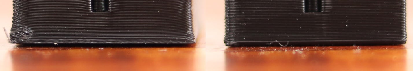
Filament Painting: Use layer swaps to stack colors, creating gradients and shading through light transmission.
Live Previews: Adjust layer thickness, color order, and TD sliders to see real-time results before printing.
Filament Library: Includes pre-calibrated TD values for brands like Polymaker, Bambu Labs, and SUNLU.
Definition: TD measures the thickness (in millimeters) at which light can penetrate a filament. A high TD (e.g., 10mm) means the filament is highly translucent, while a low TD (e.g., 1.5mm) indicates opacity.
Impact on Prints:
Opaque Filaments (low TD): Block underlying colors, ideal for bold outlines or shadows.
Translucent Filaments (high TD): Allow light to pass through, blending with layers below for gradients.
Calibration: HueForge’s built-in TD database ensures accurate predictions, but users can fine-tune values for custom filaments.
In 3D printing (especially with HueForge-style “lithophane/painting” work), TD stands for Transmission Distance, which describes how much light can pass through a filament at a given thickness. In practical terms, it is the approximate thickness of solid plastic (in millimeters) that light can penetrate before it is effectively blocked or no longer contributes to visible color blending between layers.
This means a TD of 2 would mean that after printing a part roughly 2mm thick - light transmission is low enough that deeper colors contribute very little to what you see.
Polymaker’s Panchroma filaments are optimized for HueForge’s color-blending workflows, offering a range of finishes and effects.
TD Range: Moderate translucency for balanced blending.
Applications: Matte surfaces for art prints, educational models, and ergonomic designs.
Specialty: Organic mineral additives reduce plastic content while hiding layer lines.
TD Range: Low to moderate (prioritizes photoluminescence).
Applications: Night-safe signage, glow-in-the-dark artwork, and decorative accents.
TD Range: Varies by metallic pigment density.
Applications: Space-themed lithophanes, metallic-effect gadgets, and jewelry.
TD Range: Medium-high translucency for glossy blends.
Applications: High-gloss figurines, silk-finish vases, and injection-molded-like surfaces.
TD Range: Customizable via layer thickness adjustments.
Applications: Lots more colors to add to your options.
TD Range: Customizable via layer thickness adjustments. Panchroma™ Translucent PLA is a great option for a very high TD.
Applications: A lot of unique color effects that can be utilized that were not mentioned above, including Satin, Translucent for high TD, and much more.
Pre-Baked Profiles: All Panchroma™ filaments include TD values preloaded in HueForge’s library.
AMS Compatibility: Hardened spool edges ensure smooth operation in automatic filament systems.
Mix-and-Match: Combine Matte, Glow, and Silk effects in a single print (excluding CoPE).
Import: Upload a 2D image (JPEG/PNG) into HueForge.
Color Mapping: Assign filaments to image colors using hex codes or HueForge’s palette.
TD Adjustment: Fine-tune layer thickness and order to optimize light filtering.
Export: Generate a G-code with manual or automated filament swap prompts.
Print: Use Polymaker’s Panchroma™ filaments for consistent, predictable results.
Purchasing a HueForge Personal License unlocks a $24 Polymaker coupon (US/Canada) or 23.95€ voucher (EU/UK) via 3D Jake, effectively reimbursing the software cost in filament credit. This offer applies to personal use licenses and includes free shipping on Polymaker orders.
Accessibility: Achieve multi-color artistry with single-extruder printers.
Precision: Polymaker’s TD-optimized filaments ensure HueForge’s predictions match reality.
Sustainability: Panchroma™ Matte uses biodegradable additives, aligning with eco-conscious creation.
By combining HueForge’s algorithmic brilliance with Polymaker’s material science, artists and makers can transform simple images into gallery-worthy 3D prints—proving that FDM isn’t just a tool, but a canvas.
Panchroma Matte Charcoal Black (HEX Code: #2F2E30 | TD: 0.1)
PolyLite PLA White (HEX Code: #DDD7D3)
PolyLite PLA Lemon Yellow (HEX Code: #EED230)
PolyLite PLA Azure Blue (HEX Code: #0061D5)
PolyLite PLA Red (HEX Code: #D90102)
Panchroma Matte Charcoal Black (HEX Code: #2F2E30 | TD: 0.1)
PolyLite PLA White (HEX Code: #DDD7D3)
PolyLite PLA Natural (HEX Code: #DFD3C3)
Panchroma Matte Charcoal Black (HEX Code: #2F2E30 | TD: 0.1)
PolyLite PLA White (HEX Code: #DDD7D3)
PolyLite PLA Azure Blue (HEX Code: #0061D5)
Panchroma Matte Charcoal Black (HEX Code: #2F2E30 | TD: 0.1)
PolyLite PLA White (HEX Code: #DDD7D3)
PolyLite PLA Red (HEX Code: #D90102)
PolyLite PLA Natural (HEX Code: #DFD3C3)
PolyLite PLA Lemon Yellow (HEX Code: #EED230)
PolyLite PLA Azure Blue (HEX Code: #0061D5)
Panchroma Matte Charcoal Black (HEX Code: #2F2E30 | TD: 0.1)
PolyLite PLA White (HEX Code: #DDD7D3)
PolyLite PLA Lime Green (HEX Code: #D5D701)
Panchroma Matte Charcoal Black (HEX Code: #2F2E30 | TD: 0.1)
PolyLite PLA White (HEX Code: #DDD7D3)
PolyLite PLA Red (HEX Code: #D90102)
Panchroma Matte Charcoal Black (HEX Code: #2F2E30 | TD: 0.1)
PolyLite PLA White (HEX Code: #DDD7D3)
PolyLite PLA Blue (HEX Code: #013178)
Panchroma Matte Charcoal Black (HEX Code: #2F2E30 | TD: 0.1)
PolyLite PLA White (HEX Code: #DDD7D3)
PolyLite PLA Lime Green (HEX Code: #D5D701)
Panchroma Matte Charcoal Black (HEX Code: #2F2E30 | TD: 0.1)
PolyLite PLA White (HEX Code: #DDD7D3)
PolyLite PLA Natural (HEX Code: #DFD3C3)


PolyLite PLA Lime Green (HEX Code: #D5D701)
PolyLite PLA Azure Blue (HEX Code: #0061D5)
PolyLite PLA Red (HEX Code: #D90102)
Panchroma Matte Army Brown (HEX Code: #795A4D | TD: 0.1)
PolyLite PLA Lemon Yellow (HEX Code: #EED230)
PolyLite PLA Azure Blue (HEX Code: #0061D5)
PolyLite PLA Jungle Green (HEX Code: #4E742D)